
Manual


YSI 5X00
35
YSI 5X00
34
For accurate DO measurements, ensure that the temperature reading for each DO
channel is representative of the temperature at that DO sensor’s location.
is is important when using the same temperature input source for multiple DO
sensors. Example - if the temperature source for DO1 and DO2 is the temperature
sensor connected to Aux 3 at the DO1 sensor location, it is important that the tem-
perature at the DO2 sensor location is the same as at DO1 sensor location.
See Chapter 4 Sensor Setup - page 137, for information on conguring 5X00
sensor systems. User dened sensor conguration items include:
- Display format (i.e. units of measure. For example, mg/L or % saturation,
°C or °F)
- Temperature source
- Salinity input value (user entered salinity value of the water being moni-
tored)
- Elevation monitoring system
- Setpoint, control, and alarm values and ranges
- Control and alarm relay assignments
Location Considerations
Readings gathered at the sensor location(s) are data logged and processed by the
5X00 instrument. Output control and alarm devices are congured to respond to
sensor values. erefore, it is essential to have accurate readings at the sensor loca-
tion. Locate sensors according to the below specications.
Locate sensor end of probe assembly:
• in a location that represents the entire system
• where the water ow is at least 3 inches per second (7.6 cm/sec) if using the
2.0 mil PE membrane or at least 6 inches per second (15.24 cm/sec) for 2.0
mil Teon membrane
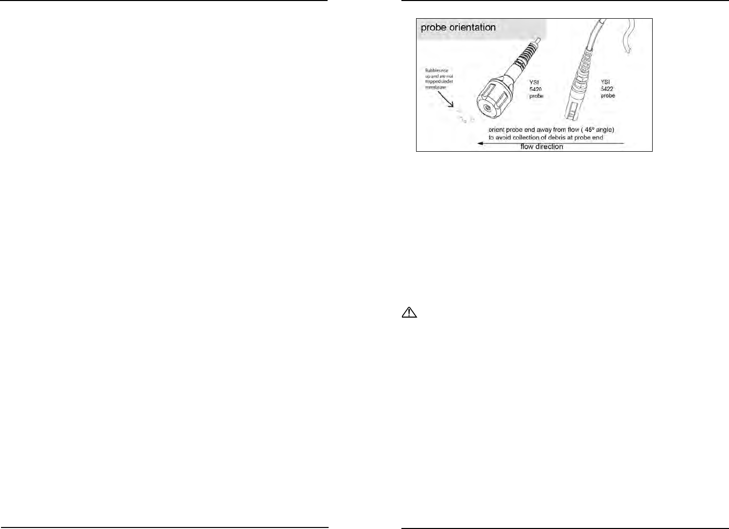
• in a location that is free from debris (e.g. algae); ideally at a 45˚ angle from
vertical position and directed with the ow - gure 3.10
5400
5400
Figure 3.10
• in a well mixed, free-owing area; midstream and mid-depth typically gives
representative readings; the probe assembly and cable are fully submersible
up to the cable connector
• submersed at all times so liquid level uctuations do not expose the sensors
to the atmosphere
• so the sensor/probe cabling is not routed near rotating machinery and/or
equipment involving electrical switching or regulation
• so that the sensor assembly and cabling are located away from sources of
electrical interference such as UV sterilizers, orescent lighting, ballasts,
pumps, any high voltage peripheral devices, etc.
CAUTION: run high and low voltage cabling through separate bulkhead and
conduit
• where regular maintenance, including calibration can easily be done. Cali-
brations are performed using the 5X00 front panel.
Note:
- e YSI 5422 DO sensor is eld replaceable and can be replaced without
replacing the probe cabling. e 5420 and 5421 DO sensors are not replace-
able. If a 5420 or 5421 sensor requires replacement, the entire probe/cable
assembly needs to be replaced.
Locate sensor end of probe assembly:
• in a location that represents the entire system
• Insert the probe into sample. Move the probe in the sample to release any
air bubbles and to provide a fresh sample to the sensor cap. is movement
is only necessary when rst inserting the probe into the sample.
5500
Installation and Wiring
Installation and Wiring