
Manual


YSI 5X00
31
YSI 5X00
30
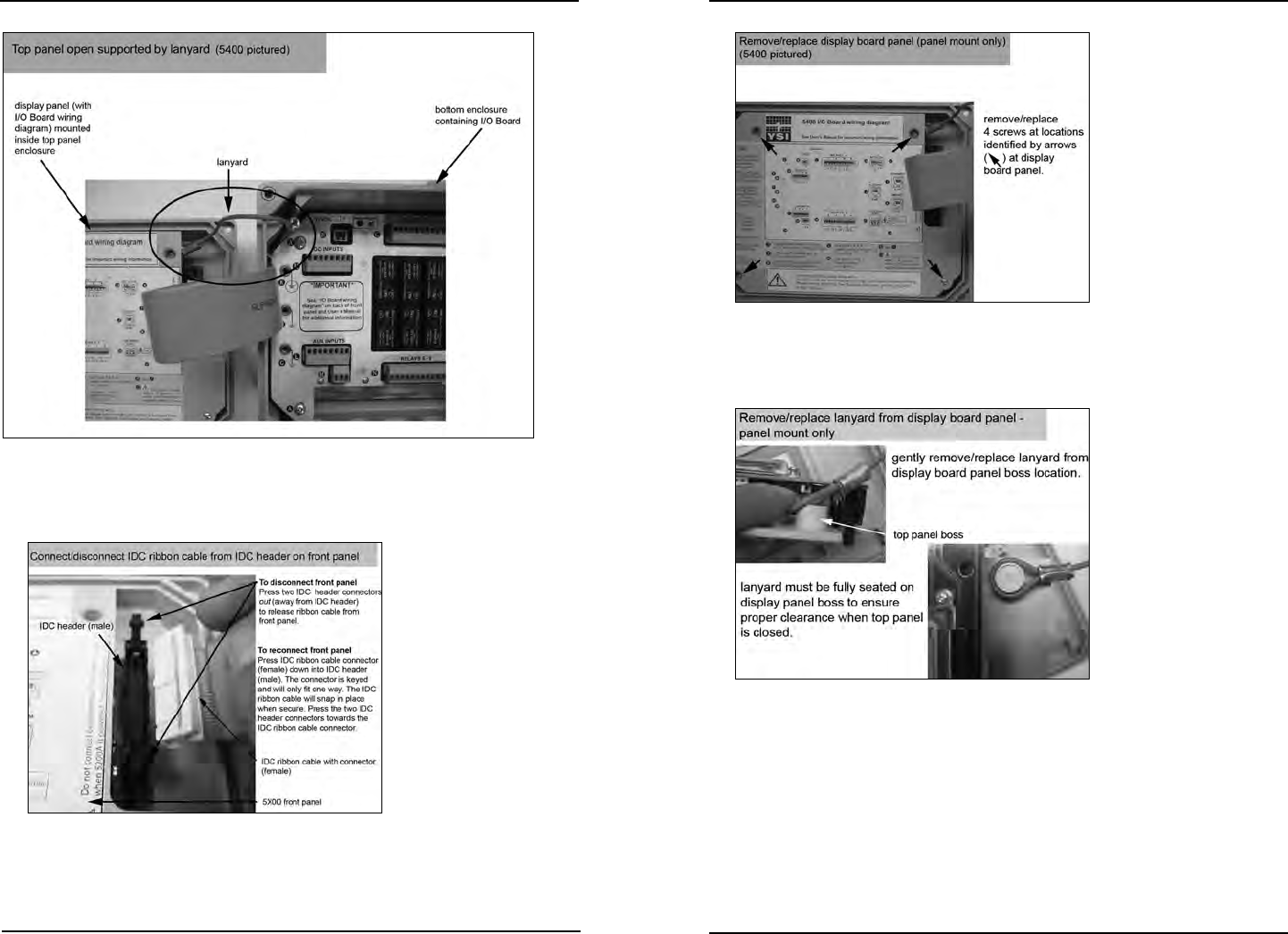
Figure 3.4
2. Disconnect front panel ribbon cable by pressing the two IDC header connec-
tors located on the front panel out (away from the IDC header) - gure 3.5.
Figure 3.5
3. Remove and retain four screws that secure display board into top panel
enclosure - gure 3.6. (Display board is mounted on panel attached to 5X00
top panel. I/O Board wiring diagram is located on the display board panel.)
Figure 3.6
4. Carefully li out the display board and remove the lanyard from the display
board panel - gure 3.7. Set display board panel and top panel aside.
Figure 3.7
5. Fasten the mounting brackets to the back of the 5X00 enclosure with the
mounting screws - gure 3.2, page 28.
6. Tighten the screws, securing the brackets to the 5X00.
7. Drill hole in panel for 5X00 enclosure (dimensions provided with kit).
8. Place standos between 5X00 mounting brackets and panel surface - gure
3.8, page 32.
9. Secure 5X00 to panel with frame using washers and bolts provided.
Installation and Wiring
Installation and Wiring