METEOROLOGICAL INSTRUMENTS INSTRUCTIONS WIND MONITOR WITH VOLTAGE OUTPUTS MODEL 05103V R.M. YOUNG COMPANY 2801 AERO PARK DRIVE, TRAVERSE CITY, MICHIGAN 49686, USA TEL: (231) 946-3980 FAX: (231) 946-4772 WEB: www.youngusa.
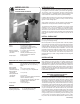
INTRODUCTION MODEL 05103V WIND MONITOR with VOLTAGE OUTPUTS The Wind Monitor measures horizontal wind speed and direction. It is rugged and corrosion resistant, yet accurate and lightweight. The housing, nose cone, propeller, and other components are injection molded U.V. stabilized plastic. Both the propeller and vertical shafts use stainless steel precision grade ball bearings. Propeller rotation produces an AC sine wave signal with frequency proportional to wind speed.
connected to the anti-static mounting post. This terminal should be connected to an earth ground (Refer to wiring diagram). Initial installation is most easily done with two people; one to adjust the instrument position and the other to observe the indicating device. After initial installation, the instrument can be removed and returned to its mounting without re-aligning the vane since the orientation ring preserves the wind direction reference. Install the Wind Monitor following these steps: 1.
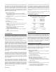
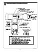
c) Loosen two set screws at base of transducer assembly and remove assembly from vertical shaft. d) Unscrew potentiometer housing from potentiometer mounting & coil assembly. e) Push potentiometer out of potentiometer mounting & coil assembly by applying firm but gentle pressure on potentiometer shaft. Make sure that the shaft o-ring comes out with the potentiometer. If not, then gently push it out from the top of the coil assembly. 4.
WARRANTY This product is warranted to be free of defects in materials and construction for a period of 12 months from date of initial purchase. Liability is limited to repair or replacement of defective item. A copy of the warranty policy may be obtained from R. M. Young Company. CE COMPLIANCE This product has been tested and shown to comply with European CE requirements for the EMC Directive. Please note that shielded cable must be used. Declaration of Conformity R. M.
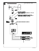
CABLE & WIRING DIAGRAM 05103V-90(H) Page 5
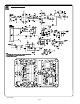
CIRCUIT DIAGRAM 05103V-90(H) Page 6
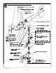
BEARING REPLACEMENT & POTENTIOMETER ADJUSTMENT 05103V-90(H) Page 7
GENERAL ASSEMBLY & REPLACEMENT PARTS 05103V-90(H) Page 8
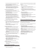
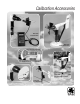
Calibration Accessories Model 18802 Anemometer Drive Model 18112 Vane Angle Bench Stand Model 18331 Vane Torque Gauge Model 18212 Vane Angle Fixture-Tower Mount Model 18310 Propeller Torque Disc Model 18301 Vane Alignment Rod
YOUNG Calibration Accessories Model 18802 Anemometer Drive provides a convenient and accurate way to rotate an anemometer shaft at a known rate. The motor may be set to rotate clockwise or counter-clockwise at any rate between 200 and 15,000 RPM in 100 RPM increments. The LCD display is referenced to an accurate and stable quartz timebase. For completely portable operation, the unit can be operated on internal batteries. For extended operation, an AC wall adapter is included.