METEOROLOGICAL INSTRUMENTS INSTRUCTIONS ULTRASONIC ANEMOMETER MODEL 85106 R.M. YOUNG COMPANY 2801 AERO PARK DRIVE, TRAVERSE CITY, MICHIGAN 49686, USA TEL: (231) 946-3980 FAX: (231) 946-4772 WEB: www.youngusa.
OPERATING INSTRUCTIONS Model 85106 Ultrasonic Anemometer Contents SECTION DESCRIPTION PAGE 1.0 SPECIFICATIONS 1 2.0 INTRODUCTION 1 3.0 INITIAL CHECKOUT 1 4.0 4.1 4.2 4.3 4.4 INSTALLATION Placement Mounting and Alignment Wiring Connections Power Requirement 2 2 2 2 2 5.0 5.1 5.2 5.3 5.4 OPERATION With Wind Tracker Display Voltage Outputs Serial Output Formats and Protocols Low Power Operation 2 2 2 2 4 6.0 6.1 6.2 6.3 6.
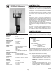
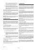
2.0 INTRODUCTION MODEL 85106 ULTRASONIC ANEMOMETER The YOUNG Ultrasonic Anemometer is a 2-axis, no-moving-parts wind sensor. It is ideal for general meteorological applications requiring accurate and reliable measurement. The sensor features wide operating range, compact size, easy installation and low power operation. Analog and digital signal outputs are available in several popular formats. The Ultrasonic Anemometer measures wind based on the transit time of ultrasonic pulses between four transducers.
.0 OPERATION The sensor wind speed threshold is preset to 0.25 m/s (0.6 mph). Wind below this level is displayed as zero. The wind direction display will show the last value that appeared when wind speed was above threshold. 3.3 5.1 WITH YOUNG MARINE WIND TRACKER DISPLAY The default serial output format is NMEA which is compatible with the Young Model 06206 Marine Wind Tracker display. The Marine Wind Tracker receives measurements in the form of ASCII data via an RS-485 serial connection.
ASCII POLAR FORMAT a www.w ddd ss*cc SDI-12 COMMAND SENSOR RESPONSE where a www.w ddd ss * cc aR0! aR1! aRC0! aRC1! a+www.w+ddd a±uu.uu±vv.vv a+www.w+ddd a±uu.uu±vv.
aI! aAb! a13 YOUNG 85000 v1.00 b a = Sensor address b = New sensor address aV! a0004 Retrieve V data with D command. Response listed next. If the prompt does not appear after receiving three ESC characters, re-check the wiring and communication program setup. If the sensor baud rate is unknown, try sending the ESC characters at each of the four available baud rates (1200, 4800, 9600, and 38400).
SET13nn SET14nn CALnn ASCII and Vout format (00=polar, 01=UV) Vout Status Code (1=none, 2=0V, 3=FS) Force Vout (00=0V, 01=5V) XX RPT ?? Go to OPERATE MODE Report parameter settings Help list 6.4.7 SET07nnnnn SET WIND SPEED MULTIPLIER All wind speed measurements are multiplied by this parameter. The default value is 10000 for a multiplier of 1.0000. This may be used to individually calibrate each sensor for improved accuracy. 6.4.8 SET08nnnnn SET WIND DIRECTION OFFSET 6.
Serial ASCII and ASCII POLLED formats report a STATUS CODE where non-zero values indicate insufficient samples or measurement error. SET14n determines how the STATUS CODE is handled in the voltage output. 7.6 SDI-12 STANDBY Serial Output Format: Output Delay: Damping Factor: Sample Count: 1 = None (ignore STATUS CODE) 2 = Set Vouts to 0V when STATUS is non-zero 3 = Set Vouts to 5V full scale when STATUS is non-zero 6.4.
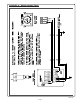
APPENDIX A: WIRING CONNECTIONS 85106-90 Page 7
APPENDIX A: WIRING CONNECTIONS 85106-90 Page 8
APPENDIX A: WIRING CONNECTIONS 85106-90 Page 9
APPENDIX A: WIRING CONNECTIONS 85106-90 Page 10
APPENDIX A: WIRING CONNECTIONS 85106-90 Page 11
APPENDIX A: WIRING CONNECTIONS 85106-90 Page 12
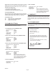
APPENDIX A: WIRING CONNECTIONS MODEL 85106 ULTRASONIC ANEMOMETER NORTH N - 0° +V (WIND FROM NORTH) EXAMPLE: WIND AT 45° W - 270° E - 90° +U (WIND FROM EAST) TOP VIEW S - 180° CARTESIAN POLAR (U-V) (SPEED, WIND DIRECTION) 170 [6.7] 407 [16.0] WHEN PROPERLY ALIGNED, JUNCTION BOX FACES SOUTH MOUNTING DEPTH 114 [4.5] MOUNTING: STANDARD 1" NPT PIPE 1.32" DIA (Ø34.0MM) ORIENTATION RING FRONT VIEW INSTALL VERTICALLY AS SHOWN TO AVOID MOISTURE DAMAGE TO CIRCUITRY.