METEOROLOGICAL INSTRUMENTS INSTRUCTIONS WIND MONITOR-SE-MA MODEL 09106 R.M. YOUNG COMPANY 2801 AERO PARK DRIVE, TRAVERSE CITY, MICHIGAN 49686, USA TEL: (231) 946-3980 FAX: (231) 946-4772 WEB: www.youngusa.
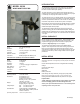
MODEL 09106 WIND MONITOR-SE-MA INTRODUCTION The Wind Monitor-SE-MA combines the performance and durability of the standard Wind Monitor with an optically encoded direction transducer and serial data output capability. The wind speed sensor is a four blade helicoid propeller that turns a multipole magnet. Propeller rotation induces a variable frequency signal in a stationary coil. Slip rings and brushes are not used. The wind direction sensor is a durable molded vane.
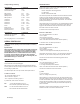
Jumper setting summary: NCAR PROTOCOL DESCRIPTION J1 POSITION Continuous serial output Polled serial output 1 IN 1 OUT RMY protocol NCAR protocol NMEA protocol RMYT protocol 2 IN 2 IN 2 OUT 2 OUT 3 IN 3 OUT 3 IN 3 OUT 1200 baud 2400 baud 4800 baud 9600 baud 4 IN 4 IN 4 OUT 4 OUT 5 IN 5 OUT 5 IN 5 OUT Knots Miles per hour Kilometers per hour Meters per second 6 IN 6 IN 6 OUT 6 OUT 7 IN 7 OUT 7 IN 7 OUT DESCRIPTION J3 POSITION &aaW: sss.
In bussed mode, commands without the “#” prefix or proper address are ignored. Properly addressed but otherwise invalid commands are responded to as follows: &aaNUc &aaNCc &aaNOc Undefined command Bad checksum Other error Where “aa” is the 09106 address in hex, 00-FF; “c” is a single character pseudo-checksum; and is the end-of-transmission character (ASCII 4). VOLTAGE OUTPUTS Voltage output mode is selected with jumper J3 in the left position.
CALIBRATION 2. INSTALL NEW BEARINGS a) Insert new front and rear bearings into nose cone. b) Replace front bearing cap. c) Carefully slide propeller shaft thru bearings. d) Place magnet on propeller shaft allowing 0.5 mm (0.020") clearance from rear bearing. e) Tighten set screw on magnet shaft collar. Do not overtighten. f) Screw nose cone into main housing until o-ring seal is seated. Be certain threads are properly engaged to avoid cross-threading.
10. ALIGN VANE a) Connect sensor to indicator. b) Install sensor on vane angle fixture (Young Model 8112 or equivalent) with junction box at 180° or South position. c) Align sensor to known angular position. If indicator output varies more than ±1 ° from known angle, loosen setscrew in direction adjust thumbwheel and slowly turn thumbwheel until correct output value is obtained. Tighten setscrew. d) Verify correct angular values at other vane positions. 11.
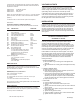
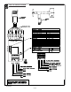
CABLE & WIRING DIAGRAM 09106-90(E) Page 6
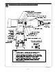
BEARING REPLACEMENT & POTENTIOMETER ADJUSTMENT 09106-90(E) Page 7
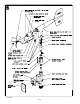
GENERAL ASSEMBLY & REPLACEMENT PARTS 09106-90(E) Page 8
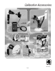
Calibration Accessories Model 18802 Anemometer Drive Model 18112 Vane Angle Bench Stand Model 18331 Vane Torque Gauge Model 18212 Vane Angle Fixture-Tower Mount Model 18310 Propeller Torque Disc Model 18301 Vane Alignment Rod 09106-90(E) Page 9
YOUNG Calibration Accessories Model 18802 Anemometer Drive provides a convenient and accurate way to rotate an anemometer shaft at a known rate. The motor may be set to rotate clockwise or counter-clockwise at any rate between 200 and 15,000 RPM in 100 RPM increments. The LCD display is referenced to an accurate and stable quartz timebase. For completely portable operation, the unit can be operated on internal batteries. For extended operation, an AC wall adapter is included.