
Technical Guide


550569-YTG-D-1212
Johnson Controls Unitary Products 11
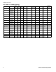
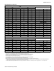
AIR HANDLER AIR FLOW DATA
HIGH/LOW SPEED COOLING AND HEAT PUMP AIRFLOW
CFM
JUMPER SETTINGS
12B 12D
High Low High Low COOL Tap ADJ Tap
1385 896 1411 907 A B
1137 745 1159 767 B B
1203 777 1227 799 A A
1019 650 1007 662 B A
1085 690 1083 716 A C
943 615 958 629 C B
889 585 908 603 B C
746 493 767 537 D B
817 537 840 568 C A
646 467 660 516 D A
738 481 780 532 C C
580 465 603 517 D C
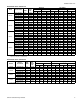
16C 20D JUMPER SETTINGS
High Low High Low COOL Tap ADJ Tap
2005 1433 2404 1579 A B
1768 1145 2022 1313 B B
2009 1299 2167 1388 A A
1615 1040 1801 1159 B A
1787 1159 1924 1256 A C
1524 988 1818 1175 C B
1445 940 1620 1024 B C
1350 883 1638 1049 D B
1384 906 1628 1030 C A
1215 800 1442 929 D A
1236 810 1434 911 C C
1086 716 1305 859 D C
HIGH/LOW SPEED ELECTRIC HEAT AIRFLOW
CFM
JUMPER SETTINGS
12B 12D
High Low High Low HEAT Tap ADJ Tap
1385 900 1411 913 A N/A
1228 795 1258 817 B N/A
1137 748 1159 769 C N/A
917 603 928 619 D N/A
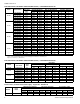
16C 20D JUMPER SETTINGS
High Low High Low HEAT Tap ADJ Tap
2006 1411 2408 1515 A N/A
1868 1243 2218 1285 B N/A
1468 983 1902 1070 C N/A
1248 840 1407 823 D N/A
1. Airflow at nominal voltage, bottom return at 0.5 external static pressure, tested without filter installed, dry coil conditions.
2. These units have variable speed motors that automatically adjust to provide constant CFM from 0.0” to 0.6” w.c. static pressure.
3. From 0.6” to 1.0” static pressure, CFM is reduced by 2% per 0.1” increase in static.
4. Operation on duct systems with greater than 1.0” w.c. external static pressure is not recommended.
5. Both the COOL and the ADJUST tap must be set to obtain the cooling airflow desired (CFM).
6. The ADJ tap does not affect the HEAT tap setting.
7. Low speed cooling used only with two stage outdoor units. (Speed is preset to 65% of high speed).
8. Dehumidification speed is 85% of jumper selected COOL tap and ADJUST tap.
9. When operating in both heat pump and electric heat modes, the airflow (CFM) will be per HEAT Tap CFM values only.
10. At some settings, LOW COOL and/or LOW HEAT airflow may be lower than what is required to operate an airflow switch on certain models of electronic air
cleaners. Consult the instructions for the electronic air cleaner for further details.
11. Airflow (CFM) indicator light (LED2) flashes once for every 100 CFM (i.e.: 12 Flashes is 1200 CFM) – blinks are approximate +/- 10% of actual CFM.