Installation & Ownerʼs Manual MINISPLIT CASSETTE AIR CONDITIONER MODELS YKCC-YKHC 12-48 YKKC 07-18 EN 035M00054-001 J391_EN.
CONTENTS Safety Precautions .................................................. 3 Part Names ............................................................... 4 Technical Specifications ......................................... 5 Dimensions ............................................................ 10 Installations............................................................ 12 Condensate Drainage ........................................... 19 Refrigerant Piping Connections...........................
REQUIRED TOOLS 1. 2. 3. 4. 5. 6. 7. 8. Screw driver Hexagonal wrench Torque wrench Spanner Reamer Hole core drill Tape measure Thermometer EXTENDED PARTS 9. 10. 11. 12. 13. 14. 15. Manifold gauge Gas leak detector Vacuum pump Pipe clamp Pipe cutter Flare tool set Electrical circuit tester 1. Refrigerant Pipe : See Technical Specification 2. Pipe insulation material (Polyethylene foam 9 mm thick) 3. Vinyl tape 4.
PART NAMES INDOOR UNIT I J K H A L G M E D F N E P O Display Panel B OUTDOOR UNIT C ■ INDOOR & OUTDOOR UNIT A. Indoor unit B. Outdoor unit C. Remote controller D. Air-in E. Air-out F. Air flow louver (at air outlet) G. Connecting pipe H. Drain hose I. Return Grill (with air filter) J. Drain pump (drain water from indoor unit) ■ DISPLAY PANEL K. Infrared signal receiver L. Emergency button M. Running indicator N. Timer indicator O.
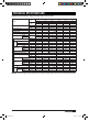
TECHNICAL SPECIFICATIONS TECHNICAL SPECIFICATION: Ceiling Cassette YKHC “R-410A” -50Hz Indoor Unit Models Outdoor Unit YKKC 12 24 30 36 48 36 48 YKJC 12 V/Ph/Hz Power Supply 18 18 24 30 220-240/1/50 380/3/50 Ph 1 1 1 3 3 3 Power Consumption W 1160/1156 1900/1900 2560/2500 3250/3250 3700/3350 4700/4900 Running Current A 6.0/6.8 8.8/8.8 12.2/11 5.5/5.5 6.5/5.8 8.2/8.
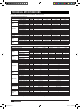
TECHNICAL SPECIFICATIONS Technical Specifications Cassette Type YKCC/YKHC12-48 R410A-50Hz York Model Power supply Capacity Cooling Input Rated current Capacity Heating Input Rated current Moisture Removal Max. input consumption Max. current Starting current Type Input Rated current (RLA) Compressor Locked rotor Amp (LRA) Thermal protector Capacitor Refrigerant oil Input Running current Indoor (Hi/Med/Lo) fan motor Capacitor Speed (Hi/Med/Lo) Number of rows Fin spacing Fin type Indoor Tube outside dia.
TECHNICAL SPECIFICATIONS Technical Specifications Cassette Type YKCC/YKHC12-48 R410A-50Hz York Model Power supply Capacity Cooling Input Rated current Capacity Heating Input Rated current Moisture Removal Max. input consumption Max. current Starting current Type Input Rated current (RLA) Compressor Locked rotor Amp (LRA) Thermal protector Capacitor Refrigerant oil Input Running current Indoor (Hi/Med/Lo) fan motor Capacitor Speed (Hi/Med/Lo) Number of rows Fin spacing Fin type Indoor Tube outside dia.
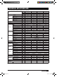
TECHNICAL SPECIFICATIONS TECHNICAL SPECIFICATION: EVEREST MULTI INVERTER “YKKC-RRJC” 50 Hz Indoor Unit Cassette Type YKKC07-18 Model YKKC07AA-AAR YKKC09AA-AAR YKKC12AA-AAR Power supply Ph-V-Hz 1Ph, 220-240V~,50Hz 1Ph, 220-240V~,50Hz 1Ph, 220-240V~,50Hz Cooling Capacity BTU/h 7,000 9,000 12,000 Capacity Heating Capacity BTU/h 8,500 11,000 14,000 Power Input W 63 63 63 Indoor fan Capacitor µF 1.5µF/450V 1.5µF/450V 1.
TECHNICAL SPECIFICATIONS TECHNICAL SPECIFICATION: CASSETTE DC INVERTER “YOHC” R-410A, 50Hz Set YKHC18DSBAAR YKHC24DSBAAR YKHC36DSBACR YKHC48DSBACR Indoor YKKC18DS-BAR YKKC24DS-BAR YKKC36DS-BCR YKKC48DS-BCR Outdoor YKJC18DS-BAR YKJC24DS-BAR YKJC36DS-BCR YKJC48DS-BCR V-Ph-Hz 220~240-1-50 220~240-1-50 380V~3~ 50Hz 380V~3~ 50Hz Btu/h 18000 24000 36000 48000 Input W 1620 2180 3280 4330 Rated current A 6.7 9.1 8.72 11.
DIMENSIONS INDOOR UNIT Drain side and Tubing side ■ YKKC 07-18 254 Nut 422 650 (Panel) 580 (Body) 600 (Ceiling hole) 611 (Hook-location) Hook Body Ceiling 67 28.
OUTDOOR UNIT ■ YKDC-YKJC 12-18 ■ YKDC-YKJC 24 313 845 895 300 135 351.2 860 695 301.5 560.1 590 163 335 330 125 235 141.5 ■ YKDC-YKJC 30-36 336.4 400 940 1245 960 990 ■ YKDC-YKJC 48 624 360 360 181.
INSTALLATIONS CAUTIONS Location in the following places may cause malfunction of the machine. (If unavoidable, please consult your local dealer) a. There is petrolatum existing. b. There is salty air surrounding (near the coast). c. There is caustic gas (the sulfide, for example) existing in the air (near a hot spring). d. The Volt varies violently (in the factories). e. In buses or cabinets. f. In kitchen where oil or gas are present. g. There is strong electromagnetic wave existing. h.
b. Select the position of installation hooks according to the hook holes on the installation board. • Drill four holes of 12 mm., 45 ~ 50 mm. deep at the selected positions on the ceiling. Then embed the expandable hooks (fittings). • Face the concave side of the installation hooks toward the expandable hooks. Determine the length of the installation hooks from the height of ceiling, then cut off the unnecessary part.
B. New built houses and ceilings a. In the case of new built house, the hook can be embedded in advance (refer to the A.b mentioned above). But it should be strong enough to bear the indoor unit and will not become loose because of concrete shrinking. b. After installing the body, fasten the installation paper board onto the air conditioner with bolts (M6 x 12) to determine in advance the sizes and positions of the hole opening on ceiling. • Refer to the A.a mentioned above for others. c. Refer to the A.
Tubing joint Hook panel Outlet joint Leakage Water-receiver Ceiling Pollution Water condensation Swing motor Chart 13 4 Loosen upper nut Hookbolt Cross-screwdriver Gap no allowed Chart 11 Body Chart 14 4-6 mm. Outlet foam Ceiling Panel sponge Panel Panel foam 1 Adjust lower nut Fan Panel foam 2 Installation coverʼs rope tap screw Slide the four slider in the corresponding channel when installing the cover.
NECESSARY ROOM FOR INSTALLATION AND MAINTENANCE (Refer to chart 17, chart 18) Remove the obstacles nearby to prevent the performance from being impeded by too little of air circulation. The minimum distance between the outdoor unit and obstacles described in the installation chart does not mean that the same is applicable to the situation of an airtight room. Leave open two of the three directions (A, B, C). >30 cm. Air inlet >30 cm. >60 cm.
INSTALLATION OF FLANGE AND DUCT Fresh air can be introduced into the unit either by installing a duct directly to the unit or adding an external fan. 4 - Ø 6 Hole NOTE 1. The device can be installed in ceiling cassette type indoor units. 2. The duct diameter is 75 mm. For different type of indoor unit, the installation methods are different and the position of holes are differed. 1. Removal the hole on the board.
Stick insulation material 4 at indoor hole Installation Type 2 Stick insulation material at the opening part of the board. Installation Type 1 Put the insulation material 4 on the interface of the hole as shown in Figure 2, then stick on the inside and surface of the board. The interface of the hole cannot have gap. Board Insulation material (inside) Board Edge Figure 2 Insulation material About 10 mm.
CONDENSATE DRAINAGE INSTALLATION The units are fitted with an internal condensate drainage pump. The hose connection point on the unit is located 260 mm. above the level of the false ceiling. Drainage piping connected to the unit must be installed with a downwards slope without any rises. Drain piping work • Drain pipe must be in downward gradient for smooth drainage. • Avoid installing the drain pipe in up and down slope to prevent reversed water flow.
REFRIGERANT PIPING CONNECTIONS ■ Fixing and Piping • Piping must be performed by qualified personnel according to good refrigeration system practices. • Piping materials and insulation materials must be of refrigerant quality. • Select the pipe diameters according to the size of unit and cut the pipe to design length by using pipe cutter. • Install the flare nuts and flare the end of the pipes. • Check that no foreign bodies are inside the piping.
WIRING DIAGRAM ■ Wiring Prepare the power source for exclusive with the air conditioner. The supply voltage must comply with the rated voltage of the air conditioner. The plug socket shall be accessible after installation. Remark: All the wiring must be based on the wiring nameplate which is shown on the model. CAUTIONS • Perform the wiring with sufficient capacity. Installation places legally require a short circuit isolator to be attached to prevent electrical shock.
YKKC 07 YKKC 09 YKKC 12 YKKC 18 RRJC 18 RRJC 27 A/F IPM(PFC) 22 J391_EN.
DC Inverter R-410A INDOOR UNIT OUTDOOR UNIT 3-core sheild cable INDOOR UNIT OUTDOOR UNIT Power supply 220-240V ~ 50Hz 1-Phase (3-core cable 3x1.0 mm2) 3-core sheild cable Power supply 220-240V ~ 50Hz 1-Phase (3-core cable 3x2.5 mm2) For 18,000-24,000 Btu/h Power supply 380-415V ~ 50Hz 3-Phase (5-core cable 5x2.5 mm2) Power supply 220-240V ~ 50Hz 1-Phase (3-core cable 3x1.
EMERGENCY OPERATIONS This function is used to operate the unit temporarily in case you misplace the remote controller or its batteries are exhausted. Two modes including AUTO and mandatory COOL can be selected through the EMERGENCY BUTTON on the air inlet grill control box of the indoor unit. Once you push this button, the air conditioner will run in such order: AUTO, mandatory COOL, OFF, and back to AUTO. EMERGENCY BUTTON 1. AUTO The RUN lamp is lit, and the air conditioner will run under AUTO mode.
Checks before operation • Check that the wiring is not broken off or disconnected. • Check that the air filter is installed. (Some air conditioners havenʼt air filters.) • Check that the outdoor unit air outlet or inlet is not blocked. Cleaning the air filter • The air filter can prevent the dust or other particulate from going inside. In case of blockage of the filter, the working efficiency of the air conditioner may greatly decrease. Therefore, the filter must be cleaned once two weeks during long time usage.
OPERATION TIPS The following events may occur during normal operation. 1. Protection of the air conditioner. Compressor protection • The compressor cannot restart for 3 minutes after it stops. Anti-cold air (Cooling and heating models only) • The unit is designed not to blow cold air on HEAT mode, when the indoor heat exchanger is in one of the following three situations and the set temperature has not been reached. A) When heating has just started. B) Defrosting. C) Low temperature heating.
TROUBLESHOOTING GUIDE Problem Probable cause Remedy A. The air conditioner does not run. 1. Power failure. 2. Fuse blown or circuit breaker open. 3. Voltage is too low. 4. Faulty contactor or relay. 5. Electrical connections loose. 6. Thermostat adjustment too low (in heating mode) or too high (in cooling mode). 7. Faulty capacitor. 8. Incorrect wiring, terminal loose. 9. Pressure switch tripped. 1. Wait for power resume. 2. Replace the fuse or reset the breaker. 3. Find the cause and fix it. 4.
DECLARATION OF CONFORMITY DECLARATION OF CONFORMITY Type of Equipment Brand Name Type Designation Air Conditioners YORK YKEA-YKDA 18/24/36/48FS, YKKA-YKJA 18/24/36/48FS, YKEB-YKDB 12/18/24/30/36/48FS, YKKB-YKJB 12/18/24/30/36/48FS, YKKC-YKJC 12/18/24/30/36/48FS YKKC-YKJC 12-48 Application of Council Directive (s) EMC Directive 89/336/EEC, Low Voltage Directive 73/23/EEC and Machine Safety Directive: MSD The following harmonized standards have been applied: Standard (s) EN 60335-1: 2002+A11 EN 60335-2-40