
Installation manual

531518-UIM-C-0110
Johnson Controls Unitary Products 13
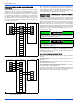
CONTROL WIRING
This furnace can be connected to the wall thermostat and outdoor A/C
or heat pump using either conventional low voltage (24 VAC) thermo-
stat wiring OR using four-wire digital communications wiring. To use
conventional low voltage wiring, see the section below entitled “Con-
ventional Low Voltage Control Wiring”. To use four-wire communica-
tions control wiring, see the section below entitled “Control Wiring using
Communicating Controls”.
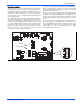
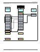
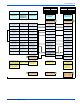
The Communicating System consists of several intelligent communicat-
ing components including the Communicating Thermostat Control
(touch-screen wall thermostat), modulating variable speed furnace, air
conditioner (15 and 18 SEER premium air conditioners) or heat pump
(13, 15 and 18 SEER premium heat pumps), which continually commu-
nicate with each other via a four-wire connection called the A-R-C-B.
Commands, operating conditions, and other data are passed continu-
ally between components over the A-R-C-B. See Figure 18. The result
is a new level of comfort, versatility, and simplicity.
In order to use this furnace in full communications (COMM) mode, it
MUST be installed with the matching touch-screen Communicating
Control (wall thermostat) and an outdoor air conditioner or heat pump
with a fully communicating control.
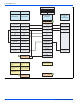
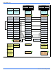
This furnace may also be used along with the Communicating Thermo-
stat Control and a non-communicating outdoor air conditioner through
the addition of a communicating Outdoor Aux Control board to the out-
door unit. This system allows full communication between the furnace
and thermostat and limited communication to the outdoor unit. See Fig-
ure 19.
This furnace may also be used along with the Communicating Thermo-
stat Control and a non-communicating outdoor air conditioner or heat
pump using COMM between the furnace and thermostat and conven-
tional 24V wiring to the outdoor unit. This system allows full communi-
cation between the furnace and thermostat but no digital
communication with the outdoor unit.
FIGURE 18: Furnace Control Board – Communications Connections
Diagnostic Light
CFM Light