
Daim Ntawv Qhia Tus Neeg Siv


1 Installing
Equalizer Kit
WARNING! This product shall only be installed,
repaired or serviced by an authorised electrician.
All applicable local, regional and national
regulations for electrical installations must be
respected.
WARNING! Turn off the power before you begin
the installation. Use extreme caution and follow
instructions carefully.
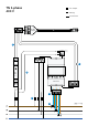
1. Mount the power meter and the 24 V-power
supply on a DIN rail in the fuse cabinet.
2. Connect the terminals for 230 V operating
current on the power meter and the
24 V-power supply. Using a separate fuse of
10A is recommended.
3. Connect the power supply 24 V terminals to
terminals V+ and V- on the modbus adapter.
4. Connect phase- and neutral conductors (PE if
IT) to the power meter voltage measurement
terminals.
5. Connect the wires from the CT-clamps to the
power meter current measurement terminals.
6. Attach one CT-clamp around each conductor
either in front of or behind the main fuse in
the fuse cabinet. Ensure that the sensors are
connected correctly, the marked arrows on
the sensors must follow the current direction
from the intake to the site.
7. Connect power meter terminals A+, B- and S
to A, B and G on the modbus adapter.
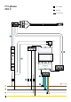
Before powering up the system, make sure that
V+ and V- are connected correctly to 24 V
power supply.
The load direction is correct on the CT
terminals and that S1 / S2 are connected
correctly to the power meter.
The phase sequence is correct on both
voltage measurement and current
measurement. The CT clamp measuring L1
should be mounted to the same phase as
connected to 10, L2 CT clamp to 11 and L3 CT
clamp to 12.
Before you start
— Please check the safety instructions on
the manufacturer’s user guides for all the
components of the kit.
— WiFi network must be enabled for the
Equalizer to work properly. Ensure that there
is an active WiFi network and note down the
login details.
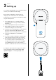
— Install the Easee Installer App on your phone
by using the QR code below.
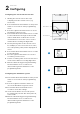
Installation
instructions