
User Manual


<14. DI Function Block>
14-1
IM 21B04C01-01E
14. DI Function Block
14.1 General
A YVP110 contains two DI function blocks, which
individually transfer the valve-position high and low
limit switch signals generated by the transducer
block.
The major functions of a DI function block include:
• Signal inversion (I/O processing option)
• Simulation
• Filtering (time delay)
• Alarm generation
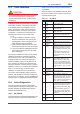
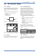
F1401.ai
DITransducer OUT_D
Figure 14.1 Inputs/Outputs of DI Function Block
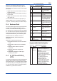
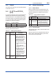
F1402.ai
Output
OUT_D
FIELD_VAL_D
Simulate
SIMULATE_D
Optional
Invert
Alarms
DISC
MODE
Filter
PV_FTIME
CHANNEL PV_D
Figure 14.2 Function Diagram of DI Function Block
14.2 Modes
The target mode for a DI function block can be set
from three block modes: O/S, Auto, and Man.
14.3 PV Value (PV_D)
A limit switch signal is transferred from the
transducer block via a channel. Normally, the
Transducer Value and Transducer Status values
in SIMULATE_D are copied to FIELD_VAL_D,
indicating the on/off status of the corresponding
limit switch. If SIMULATE_D is set to 'Enable',
the Simulate Value and Simulate Status values in
SIMULATE_D are copied to FIELD_VAL_D.
SIMULATE_D contains the following data:
Simulate Status: Status to be set in simulation
mode
Simulate Value: Value to be set in simulation
mode
Transducer Status: Status of input from
transducer
Transducer Value: Value of input from
transducer
Enable/Disable: Whether to enable (2) or
disable (1) simulation
The value of FIELD_VAL_D is copied to the
process value PV_D. At this time, if the Invert
option (bit 0) is specied as true, the on/off status is
inverted.
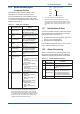
Table 14.1 FIELD_VAL_D
Value of FIELD_VAL_D
Value of PV_D
Invert = False Invert = True
0 0 (off) 1
≥1 1 (on) 0
14.4 Filtering
Transfer of a change in the value of FIELD_VAL_D
to the value of PV_D can be delayed for a desired
time period set in the parameter PV_FTIME (in
seconds).