
User Manual


<1. Notes on Handling>
1-9
IM 21B04C01-01E
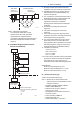
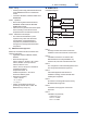
I.S. values Power supply-eld device:
Po ≤ Pi, Uo ≤ Ui, Io ≤ Ii
Calculation of max. allowed cable length:
Ccable ≤ Co - ∑ci - ∑ci (Terminator)
Lcable ≤ Lo - ∑Li
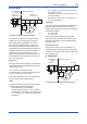
Number of Devices
The number of devices (max. 32) possible on a
eldbus link depends on factors such as the power
consumption of each device, the type of cable used,
use of repeaters, etc.
B) ATEX Flameproof Type
Caution for ATEX ameproof type.
Note 1. Model YVP110 Valve Positioner with
optional code /KF2 is applicable for
potentially explosive atmospheres:
• Applicable standard:
EN60079-0:2009, EN60079-1:2007
• Certicate: KEMA 10ATEX0023 X
• Group: II
• Category: 2G
• Type of Protection and Marking Code:
Ex d IIC, T6 or T5 Gb
• Ambient Temperature: T6; –40 to 65°C
T5; –40 to 80°C
Note 2. Electrical Data
• Supply voltage: 32 V DC max.
• Output signal: 17 mA DC
Note 3. Installation Instructions
• The cable glands and blanking elements
shall be certied in type of protection
ameproof enclosure “d” suitable for the
conditions of use and correctly installed.
• With the use of conduit entries a sealing
device shall be provided either in the
ameproof enclosure or immediately on the
entrance thereto.
• To maintain the degree of ingress protection
IP65 according to EN 60529 special care
must be taken to avoid water entering the
breathing and draining device when the valve
positioner is mounted with the feedback shaft
in the upright position.
Note 4. Operation
• Keep strictly the WARNING on the label on
the positioner.
AFTER DE-ENERGIZING, DELAY 5
MINUTES BEFORE OPENING.
WHEN THE AMBIENT TEMP. ≥ 70°C,
USE HEAT-RESISTING CABLE & CABLE
GLAND ≥ 90°C.
Note 5. Maintenance and Repair
• The instrument modication or parts
replacement by other than authorized
representative of Yokogawa Electric
Corporation is prohibited and will void KEMA
Flameproof Certication.
C)
ATEX Intrinsically safe (Ex ic)/Type n (Ex nA)
Note 1. Model YVP110 Advanced Valve Positioner
with optional code /KN25
• Applicable standard:
EN60079-0:2009/EN60079-0:2012(Ex ic/Ex
nA), EN60079-11:2012(Ex ic)
EN60079-15:2010(Ex nA)
• Ex ic: II 3G Ex ic IIC T4 Gc (Intrinsically safe)
• Ex nA: II 3G Ex nA IIC T4 Gc (Non-sparking)
• Ambient Temperature: -30 to 75°C
• Ambient Humidity:
0 to 100%RH (No condensation)
• Enclosure: IP65
• Installation category: I
Note 2. Electrical Data
• Ex ic: Ui = 32 V, Ci = 3.52 nF, Li = 0 μH
• Ex nA: 32 V DC MAX
Note 3. For the installation of this positioner, once
a particular declared type of protection
is selected, the other type of protection
cannot be used. The installation must be in
accordance with the description about type
of protection in this instruction manual.
Note 4. In order to avoid confusion, unnecessary
marking is crossed out on the label other
than the selected type of protection when
positioner is installed.
Note 5. Installation Instructions
• Cable glands, adapters and/or blanking
elements shall be of Ex “n”, EX “e” or Ex “d”
and shall be installed so as to maintain the
specied degree of protection (IP Code) of
the equipment.
• To maintain the degree of protection IP65
according to IEC 60529, special care must
be taken to avoid water.
Note 6. Maintenance and Repair
• The instrument modication or parts
replacement by other than authorized
representative of Yokogawa Electric
Corporation is prohibited and will void ATEX
Ex ic and Ex nA.