
User Manual


<2. Part Names>
2-1
IM 01C50T02-01E
2. Part Names
Refer to the individual instruction manuals for
detailed descriptions of the parts. This section
describes the topics applicable to the Fieldbus
communication type.
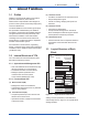
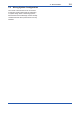
(1) In the Fieldbus communication type, the
amplier(CPU) assembly consists of two
boards, as shown in Figure 2.1.
(2) In other communication types, there's the pin
switch which is used for selecting the direction
of hardware burnout at the position of 'SW1'
on the amplier assembly, while Fieldbus
communication type does not have this pin.
(3) The Fieldbus communication type has a
simulation function. A SIMULATE-ENABLE
switch is mounted at 'SW1' on the amplier.
Refer to Section 6.3, “Simulation Function” for
details of the simulation function.
Simulation
setting switch
Amplifier Assembly
F0201.ai
Figure 2.1 Diagram of the Amplier Assembly