
User Manual


<8. Handling Caution>
8-4
IM 01C50T02-01E
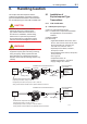
Supply unit
The supply unit must be certied by a notify body
as FISCO model and following trapezoidal or
rectangular output characteristic is used.
Uo = 14 . . . 24 V (I.S. maximum value)
Io based on spark test result or other assessment,
ex. 133 mA for Uo = 15 V (Group IIC, rectangular
characteristic)
No specication of Lo and Co in the certicate and
on the label.
Cable
The cable used to interconnect the devices needs
to comply with the following parameters:
loop resistance R’: 15 . . . 150 Ω/km
inductance per unit length L’: 0.4 . . . 1 mH/km
capacitance per unit length C’: 80 . . . 200 nF/km
C’ = C’ line/line + 0.5 C’ line/screen, if both lines
are oating
or
C’ = C’ line/line + C’ line/screen, if the screen is
connected to one line
length of spur cable: max. 30 m (EEx ia IIC T4)
or 120 m (EEx ia IIB T4)
length of trunk cable: max. 1 km (EEx ia IIC T4)
or 1.9 km (EEx ia IIB T4)
Terminators
The terminator must be certied by a notify body as
FISCO model and at each end of the trunk cable
an approved line terminator with the following
parameters is suitable:
R = 90 . . . 100 Ω
C = 0 . . . 2.2 µF.
The resistor must be infallible according to IEC
60079-11. One of the two allowed terminators might
already be integrated in the associated apparatus
(bus supply unit).
FIELD INSTRUMENTS
Intrinsically safe ratings of the transmitter (FIELD
INSTRUMENTS) are as follows:
Supply/output circuit
EEx ia IIC T4
Maximum Voltage (Ui) = 17.5 V
Maximum Current (Ii) = 360 mA
Maximum Power (Pi) = 2.52 W
Internal Capacitance (Ci) = 1.5 nF
Internal Inductance (Li) = 8µH
EEx ia IIB T4
Maximum Voltage (Ui) = 17.5 V
Maximum Current (Ii) = 380 mA
Maximum Power (Pi) = 5.32 W
Internal Capacitance (Ci) = 1.5 nF
Internal Inductance (Li) = 8 µH
Sensor circuit
EEx ia IIC T4
Maximum Voltage (Uo) = 7.7 V
Maximum Current (Io) = 70 mA
Maximum Power (Po) = 140 mW
External Capacitance (Co) = 1.6 µF
External Inductance (Lo) = 7.2 mH
Number of Devices
The number of devices (max. 32) possible on a
eldbus link depends on factors such as the power
consumption of each device, the type of cable used,
use of repeaters, etc.
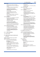
(2) Entity Model
Non-Hazardous
Locations
Hazardous Locations
F0803.ai
Terminator
Ex i
Field Instruments
(Passive)
Hand-
held-
Terminal
Supply Unit
Terminator
Data
U
U
I
YTA
1 23 4 5
Supply
Sensor
I.S. eldbus system complying with Entity
model
I.S. values Power supply-eld device:
Po ≤ Pi, Uo ≤ Ui, Io ≤ Ii
Calculation of max. allowed cable length:
Ccable ≤ Co - Σci - Σci (Terminator)
Lcable ≤ Lo - ΣLi
FIELD INSTRUMENTS
Intrinsically safe ratings of the transmitter (FIELD
INSTRUMENTS) are as follows:
Supply/output circuit
EEx ia IIC T4
Maximum Voltage (Ui) = 24.0 V
Maximum Current (Ii) = 250 mA
Maximum Power (Pi) = 1.2 W
Internal Capacitance (Ci) = 1.5 nF
Internal Inductance (Li) = 8 µH