
User Manual


<7. Errors and Warnings>
7-1
IM 01C50T02-01E
7. Errors and Warnings
7.1 Error and Warning
Indications
Faults found as a result of self-diagnostics by a
YTA320 are identied as errors or warnings. Errors
are abnormalities in the physical device, such as a
hardware failure or communication error. Warnings
are problems in the parameter settings or abnormal
operation status of the device, such as the active
state of the bypass action and simulation mode,
in order to alert the user. The user can check the
errors and warnings currently occurring in a YTA320
with either of the following:
• Value (bit statuses) in DEVICE_STATUS_1 to
_8 of the resource block
• Error code displayed on the LCD (for a model
with a built-in LCD)
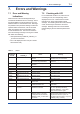
7.2 Checking with LCD
For a YTA320 with a built-in LCD, when an error
or warning occurs, the corresponding code is
displayed on the LCD. Codes AL001 to AL085
indicate errors, and AL100 and later indicate
warnings. The following shows the code, indication,
cause, and remedy for each of the errors and
warnings. Warnings and errors can be masked
independently by the user if desired (see Section
5.6.4).
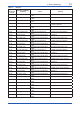
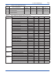
Table 7.1 Errors
Code
Displayed
on LCD
Indication of DEVICE_
STATUS_#
Cause Remedy
- - - — YTA does not participate in the
network.
Check the communication related
parameters. See A.5.2 for details.
The AI block to be displayed on
the LCD is not yet scheduled.
Check the setting of DISPLAY_AI_OUT
in TB block.
AL001 No Response From AD
Board
Failure in input circuitry of
hardware
Make a service call.
AL003 EEPROM failure EEPROM failure Make a service call.
AL004 Flash ROM SUM Error Flash ROM failure Make a service call.
AL005 PPM Communication Error Internal communication error Make a service call.
AL006 Parsley Receive Error Internal communication error Make a service call.
AL007 AMP Temp Counter Too
High
Hardware failure Make a service call.
AL008 AMP Temp Counter Too
Low
Hardware failure Make a service call.
AL010 WDT 3 Times Over Error Hardware failure Make a service call.
AL021 RB in O/S Mode The actual mode of the resource
block is O/S.
Set the target mode of the resource block
to Auto.
AL022 TB in O/S Mode The actual mode of the
transducer block is O/S.
Set the target mode of the transducer
block to Auto.
AL030 Start Backup Mode of
Channel6
The backup sensor input is
selected for channel 6.
Restore the sensor 1 input to normal.
Then, set 1 (Enable) in BACKUP_
RETURN_SENSOR1, or turn off the
power once and back on again.
AL031 Not Used Sensor1 Although a channel number
related to sensor 1 (see note)
is assigned to an AI or DI block,
SENSOR_TYPE_1 is set to Non-
connection.
Do not assign to any AI or DI block a
channel number related to sensor 1 (see
note) when the sensor 1 input is not
used. When using the sensor 1 input, set
SENSOR_TYPE_1 correctly.