User’s Manual YTA Series Temperature Transmitter Fieldbus Communication IM 01C50T02-01E IM 01C50T02-01E 8th Edition
1 YTA series Temperature Transmitter Fieldbus Communication IM 01C50T02-01E 8th Edition CONTENTS 1. Introduction................................................................................................ 1-1 ■ Regarding This Manual................................................................................................. 1-1 ■ For Safe Use of Product................................................................................................ 1-2 ■ Warranty...................................
2 6. 7. 8. Parameters of Transducer Block...................................................... 5-12 5.6.5 Parameters of AI Function Block...................................................... 5-14 5.6.6 Parameters of DI Function Block...................................................... 5-15 5.6.7 A setting when Sensor input 2 is not connected............................... 5-15 In-process Operation................................................................................ 6-1 6.
3 Appendix 4. PID Block....................................................................................A4-1 A4.1 Function Diagram........................................................................................... A4-1 A4.2 Functions of PID Block................................................................................... A4-1 A4.3 Parameters of PID Block................................................................................ A4-2 A4.4 PID Computation Details...............
1. 1-1 <1. Introduction> Introduction This manual contains a description of the YTA320 Temperature Transmitter Fieldbus Communication Type. The Fieldbus communication type is based on the same dual sensor input features as that of the BRAIN or HART communication type and is similar to the BRAIN or HART communication type in terms of basic performance and operation. This manual describes only those topics that are required for operation of the Fieldbus communication type.
■ For Safe Use of Product For the protection and safety of the operator and the instrument or the system including the instrument, please be sure to follow the instructions on safety described in this manual when handling this instrument. In case the instrument is handled in contradiction to these instructions, Yokogawa does not guarantee safety. Please give your attention to the followings. (a) Installation • The instrument must be installed by an expert engineer or a skilled personnel.
<1. Introduction> 1-3 ■ ATEX Documentation This procedure is only applicable to the countries in European Union.
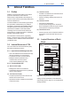
2. <2. Part Names> 2-1 Part Names Refer to the individual instruction manuals for detailed descriptions of the parts. This section describes the topics applicable to the Fieldbus communication type. (1) In the Fieldbus communication type, the amplifier(CPU) assembly consists of two boards, as shown in Figure 2.1.
3. 3.1 About Fieldbus Outline Fieldbus is a bi-directional digital communication protocol for field devices, which offers an advancement in implementation technologies for process control systems and is widely employed by numerous field devices. YTA Series Fieldbus communication type employs the specification standardized by The Fieldbus Foundation, and provides interoperability between Yokogawa devices and those produced by other manufacturers.
3.4 <3. About Fieldbus> 3-2 Wiring System Configuration The number of devices that can be connected to a single bus and the cable length vary depending on system design. When constructing systems, both the basic and overall design must be carefully considered to allow device performance to be fully exhibited.
4. Getting Started Fieldbus is fully dependent upon digital communication protocol and differs in operation from conventional 4 to 20 mA transmission and the BRAIN or HART communication protocol. It is recommended that novice users use field devices in accordance with the procedures described in this section. The procedures assume that field devices will be set up on a bench or an instrument shop. 4.1 4-1 <4.
4.2 <4. Getting Started> Host Setting 4.3 To activate Fieldbus, the following settings are required for the host. IMPORTANT Do not turn off the power immediately after setting. When the parameters are saved to EEPROM, the redundant processing is executed for the improvement of reliability. If the power is turned off within 60 seconds after setting is made, the modified parameters are not saved and the settings may return to the original values. Table 4.
4.4 Integration of DD If the host supports DD (Device Description), the DD of the YTA needs to be installed. Check if host has the following directory under its default DD directory. 594543\0005 (594543 is the manufacturer number of Yokogawa Electric Corporation, and 0005 is the YTA device number, respectively.) If this directory is not found, DD of YTA has not been included. Create the above directory and copy the DD file (0m0n.ffo,0m0n.sym) (m, n is a numeral) into the directory.
5. <5. Configuration> 5-1 Configuration This chapter contains information on how to adapt the function and performance of the YTA to suit specific applications. Because two or more devices are connected to Fieldbus, settings including the requirements of all devices need to be determined. Practically, the following steps must be taken. (1) Network design Determines the devices to be connected to Fieldbus and checks the capacity of the power supply.
5.2 Network Definition 0x00 Before connection of devices with Fieldbus, define the Fieldbus network. Allocate PD Tag and node addresses to all devices (excluding such passive devices as terminators). The PD Tag is the same as the conventional one used for the device. Up to 32 alphanumeric characters may be used for definition. Use a hyphen as a delimiter as required. The node address is used to specify devices for communication purposes.
5.3 Definition of Combining Function Blocks The input/output parameters for function blocks are combined. For the YTA, four AI blocks output parameter (OUT), four DI blocks output parameter (OUT_D) and PID block are subject to combination. They are combined with the input of the control block as necessary. Practically, setting is written to the YTA link object with reference to “Block setting” in Section 5.6 for details.
5.4 Setting of Tags and Addresses 5.5 This section describes the steps in the procedure to set PD Tags and node addresses in the YTA. There are three states of Fieldbus devices as shown in Figure 5.4, and if the state is other than the lowest SM_OPERATIONAL state, no function block is executed. YTA must be transferred to this state when an YTA tag or address is changed.
Table 5.4 VCR Static Entry SubParameter index 1 FasArTypeAndRole 2 3 4 5 6 7 8 9 10 11 5-5 <5. Configuration> Description Indicates the type and role of communication (VCR). The following 4 types are used for YTA. 0x32: Server (Responds to requests from host.) 0x44: Source (Transmits alarm or trend.) 0x66: Publisher (Sends AI block output to other blocks.) 0x76: Subscriber (Receives output of other blocks by PID block.) FasDllLocalAddr Sets the local address to specify VCR in YTA.
5.6 Block Setting 5.6.2 Trend Object Set the parameter for function block VFD. 5.6.1 Link Object Link object combines the data voluntarily sent by the function block with VCR. YTA has 26 link objects. A single link object specifies one combination. Each link object has the parameters listed in Table 5.6. Parameters must be changed together for each VCR because the modifications made to each parameter may cause inconsistent operation. Table 5.
5-7 <5. Configuration> 5.6.3 View Object This is the object to form groups of parameters in a block. One of advantage brought by forming groups of parameters is the reduction of load for data transaction. YTA has four View Objects for each Resource block, Transducer block and each function block, and each View Object has the parameters listed in Table 5.11 to 5.13. Table 5.10 Description Set of dynamic parameters required by operator for plant operation. (PV, SV, OUT, Mode etc.
Table 5.12 Relative index 1 2 3 4 5 6 7 8 9 10 11 12 13 14 15 16 17 18 19 20 21 22 23 24 25 26 27 28 29 30 31 32 33 34 35 36 37 38 39 40 41 42 43 44 45 46 47 48 49 50 5-8 <5.
Relative index 51 52 53 54 55 56 57 58 59 60 61 62 63 64 65 66 67 68 69 70 71 72 73 74 75 76 77 78 79 80 81 82 83 84 85 86 87 88 89 90 91 92 93 94 95 96 97 98 99 100 5-9 <5.
Relative index 101 102 103 104 105 106 107 108 109 110 111 112 113 114 115 116 5-10 <5.
Table 5.13 View Object for AI Function Block Relative index Parameter 1 2 3 4 5 6 7 8 9 10 11 12 13 14 15 16 17 18 19 20 21 22 23 24 25 26 27 28 29 30 31 32 33 34 35 36 5-11 <5.
5.6.4 Parameters of Transducer Block The transducer block makes settings for the temperature transmitter-specific functions of the YTA320, such as the temperature input and display settings. See Appendix 1 for a list of all parameters of the YTA320; this section describes only the settings for important parameters. Note that you can choose “˚C” or “Kelvin” as the unit of temperature. “˚F” or “˚R” can also be selected for a model with the option code /D2.
If you want to switch back to select sensor 1 input while the backup action is active after the sensor 1 input recovers, set 1 (Enable) in BACKUP_RETURN_SENSOR1. Because this data is not retained, set 1(Enable) in the parameter every switch back. When there is no connection to sensor 2 input, the status of BACKUP_VALUE is Bad and the value is undefined.
CAL_POINT_HI_1 (2), CAL_POINT_LO_1 (2) These parameters store the calibrated upper and lower range limit values for sensor input 1 (or 2). To perform a calibration, apply a voltage (for a thermocouple or voltage input) or a resistance (for a RTD or resistance input) between the corresponding input terminals, and write the applied level to these parameters.
PV_FTIME Stipulates the time constant (in seconds) of the first-order lag filter inside the AI block. OUT_SCALE Stipulates the range of OUT (by setting the upper and lower range limits). The unit can also be set freely. OUT_SCALE is set to 0 to 100% before the YTA320 is shipped from the factory. Change the setting as necessary.
6. 6.1 6-1 <6. In-process Operation> In-process Operation Mode Transition All function blocks have modes. All blocks have their mode, expressed by MODE_BLK parameter. It is a structure of four components; Target, Actual, Permitted and Normal. Target : Sets the operating condition of the block. Actual : Indicates the current operating condition. Permit : Indicates the operating condition that the block is allowed to take. Normal: Indicates the operating condition that the block will usuall y take.
Table 6.1 Alert Object Table 6.2 Analog Alert Discrete Alert Update Alert Subindex 1 1 1 2 2 2 3 3 3 4 4 4 5 5 5 6 7 6 7 6 7 8 8 9 10 9 10 8 11 6.3 11 6-2 <6.
6-3 <6. In-process Operation> Following figure shows the items shown on a display. (5) (4) (1) (2) (3) F0603.ai Figure 6.3 LCD Display Five-digit LCD Display (1) Shows Output value(OUT) of AI block, Address, and Error Codes(AL XXX). Shows "-----" when the communication has not been established, for example immediately after power on, or when AI block is not scheduled.
7. 7.1 <7. Errors and Warnings> 7-1 Errors and Warnings 7.2 Error and Warning Indications Checking with LCD For a YTA320 with a built-in LCD, when an error or warning occurs, the corresponding code is displayed on the LCD. Codes AL001 to AL085 indicate errors, and AL100 and later indicate warnings. The following shows the code, indication, cause, and remedy for each of the errors and warnings. Warnings and errors can be masked independently by the user if desired (see Section 5.6.4).
<7.
Table 7.2 7-3 <7.
Code Displayed on LCD AL150 PID2 in Bypass active AL160 Sensor1 Temp Too High AL161 Sensor1 Temp Too Low AL170 Sensor2 Temp Too High AL171 Sensor2 Temp Too Low AL190 Stop Detection of Sensor Burnout AL191 Illegal Unit of AI1 AL192 Illegal Unit of AI2 AL193 Illegal Unit of AI3 AL194 Illegal Unit of AI4 AL198 Default Address Mode Table 7.3 7-4 <7. Errors and Warnings> Indication of DEVICE_ STATUS_# Cause The bypass action for PID2 is active.
7.3 7-5 <7. Errors and Warnings> Checking with DEVICE_STATUS_1 to _8 of Resource Block When faults occur, the corresponding bits in the parameters DEVICE_STATUS_1 to _8 of the resource block are set to on. Table 7.4 shows the codes and indications corresponding to the individual bits in DEVICE_STATUS_1 as well as the meanings represented. Tables 7.5 to 7.10 Table 7.
Table 7.5 Hexadecimal Indication 0x8000 0000 0x4000 0000 0x2000 0000 0x1000 0000 0x0800 0000 0x0400 0000 0x0200 0000 0x0100 0000 0x0080 0000 0x0040 0000 0x0020 0000 0x0010 0000 0x0008 0000 0x0004 0000 0x0002 0000 0x0001 0000 0x0000 8000 0x0000 4000 0x0000 2000 0x0000 1000 0x0000 0800 0x0000 0400 0x0000 0200 0x0000 0100 0x0000 0080 0x0000 0040 0x0000 0020 0x0000 0010 0x0000 0008 0x0000 0004 0x0000 0002 0x0000 0001 7-6 <7.
Table 7.7 Hexadecimal Indication 0x8000 0000 0x4000 0000 0x2000 0000 0x1000 0000 0x0800 0000 0x0400 0000 0x0200 0000 0x0100 0000 0x0080 0000 0x0040 0000 0x0020 0000 0x0010 0000 0x0008 0000 0x0004 0000 0x0002 0000 0x0001 0000 0x0000 8000 0x0000 4000 0x0000 2000 0x0000 1000 0x0000 0800 0x0000 0400 0x0000 0200 0x0000 0100 0x0000 0080 0x0000 0040 0x0000 0020 0x0000 0010 0x0000 0008 0x0000 0004 0x0000 0002 0x0000 0001 7-7 <7.
Table 7.9 Hexadecimal Indication 0x8000 0000 0x4000 0000 0x2000 0000 0x1000 0000 0x0800 0000 0x0400 0000 0x0200 0000 0x0100 0000 0x0080 0000 0x0040 0000 0x0020 0000 0x0010 0000 0x0008 0000 0x0004 0000 0x0002 0000 0x0001 0000 0x0000 8000 0x0000 4000 0x0000 2000 0x0000 1000 0x0000 0800 0x0000 0400 0x0000 0200 0x0000 0100 0x0000 0080 0x0000 0040 0x0000 0020 0x0000 0010 0x0000 0008 0x0000 0004 0x0000 0002 0x0000 0001 7-8 <7.
Table 7.11 Case 1 2 3 Example of Warning Masking Settings Device Configurations Sensor 2 is not used. Only AI1 is used. Sensors 1 and 2 are used. AI1 and AI2 are used. Sensors 1 and 2 are used. AI1 and DI1 are used. Table 7.12 Parameter WARNING_ ENABLE_1 WARNING_ ENABLE_2 WARNING_ ENABLE_3 WARNING_ ENABLE_4 7-9 <7.
8. 8-1 <8. Handling Caution> Handling Caution This chapter describes important cautions regarding the installation of explosion protected type for FOUNDATION Fieldbus YTA transmitters. For JIS flameproof type, refer to IM 01C50B01-01E. 8.1 Installation of Explosionproof Type Transmitters 8.1.1 CSA Certification CAUTION This instrument is tested and certified as intrinsically safe type or explosionproof type.
Note 2. Wiring * All wiring shall comply with Canadian Electrical Code Part I and Local Electrical Codes. * In hazardous location, wiring shall be in conduit as shown in the figure. * WARNING: A SEAL SHALL BE INSTALLED WITHIN 50 cm OF THE ENCLOSURE. UN SCELLEMENT DOIT ÊTRE INSTALLÉ À MOINS DE 50 cm DU BOÎTIER. * When installed in Division 2, “FACTORY SEALED, CONDUIT SEAL NOT REQUIRED”. Note 3. Operation * Keep strictly the “WARNING” on the label attached on the transmitter.
* When combined with FISCO model IIC barrier Ui = 17.5 V, Ii = 360 mA, Pi = 2.52 W, Ci = 1.5 nF, Li = 8 µH * When combined with barrier Ui = 24.0 V, Ii = 250 mA, Pi = 1.2 W, Ci = 1.5 nF, Li = 8 µH • EEx ia IIB T4 Type of Protection and Marking Code: EEx ia IIB T4 Group: II Category: 1G Ambient Temperature: –40 to 60°C Degree of Protection of the Enclosure: IP67 Electrical Data * When combined with FISCO model IIB barrier Ui = 17.5 V, Ii = 380 mA, Pi = 5.32 W, Ci = 1.
Supply unit The supply unit must be certified by a notify body as FISCO model and following trapezoidal or rectangular output characteristic is used. Uo = 14 . . . 24 V (I.S. maximum value) Io based on spark test result or other assessment, ex. 133 mA for Uo = 15 V (Group IIC, rectangular characteristic) No specification of Lo and Co in the certificate and on the label. Cable The cable used to interconnect the devices needs to comply with the following parameters: loop resistance R’: 15 . . .
8-5 <8. Handling Caution> Sensor circuit EEx ia IIC T4 Maximum Voltage (Uo) = 7.7 V Maximum Current (Io) = 70 mA Maximum Power (Po) = 140 mW External Capacitance (Co) = 1.6 µF External Inductance (Lo) = 7.2 mH Number of Devices The number of devices (max. 32) possible on a fieldbus link depends on factors such as the power consumption of each device, the type of cable used, use of repeaters, etc. C) ATEX Intrinsically Safe “ic” Caution for ATEX Intrinsically Safe “ic” Note 1.
<8. Handling Caution> 8-6 (6) Name Plate (2) Electrical Connection The type of electrical connection is stamped near the electrical connection port according to the following marking. Name plate for intrinsically safe type TEMPERATURE TRANSMITTER MODEL YTA SUFFIX NO. OUTPUT CAL RNG STYLE SUPPLY *3 T0801.ai Location of the marking F0805.ai (3) Installation Name plate for flameproof type TEMPERATURE TRANSMITTER MODEL YTA SUFFIX STYLE SUPPLY NO.
<8. Handling Caution> *1: The production year The third figure from the left of the serial number shows the year of production. The relation between the third figure and the production year is shown below. Third figure D E F G H J K Production year 2004 2005 2006 2007 2008 2009 2010 For example, the production year of the product engraved in “NO.” column on the name plate as follows is 2007. C2G218541 2007 *2: “180-8750” is a zip code which represents the following address.
<8. Handling Caution> IFM018-A12 Installation Diagram (Intrinsically safe, Division 1 Installation) Terminator Temperature 1 Transmitter 2 3 SUPPLY SENSOR 4 5 Transmitter Transmitter Hazardous Location Non Hazardous Location Terminator Safety Barrier F0807.ai *1: *2: *3: *4: *5: *6: *7: *8: Dust-tight conduit seal must be used when installed in Class II and Class III environments. Control equipment connected to the Associated Apparatus must not use or generate more than 250 Vrms or Vdc.
The allowed voltage Uo of the associated apparatus used to supply the bus is limited to the range of 14 V dc to 24 V dc. All other equipment connected to the bus cable has to be passive, meaning that the apparatus is not allowed to provide energy to the system, except to a leakage current of 50 µA for each connected device.
*4: Associated Nonincendive Field Wiring Apparatus manufacturer’s installation drawing must be followed when installing this equipment. *5: No revision to drawing without prior FM Approvals. *6: Terminator and supply unit must be FM Approved. *7: If use ordinary wirings, the general purpose equipment must have nonincendive field wiring terminal approved by FM Approvals.
<8. Handling Caution> Installation Diagram (Installation Diagram for Intrinsically Safe) Terminator + Temperature 1 Transmitter 2 3 – SUPPLY C(*) SENSOR 4 5 + Transmitter – + Transmitter – Hazardous Location Non Hazardous Location Terminator (*)‘C’ and ‘–’ may be shorted. + – Safety Barrier + – 8-11 Electrical Data: • Supply Input (+ and –) Maximum Input Voltage Ui: 24 V *1 Maximum Input Current Ii: 250 mA *1 Maximum Input Power Pi: 1.2 W *1 Maximum Internal Capacitance Ci: 1.
8-12 <8. Handling Caution> Supply unit System evaluations Trapezoidal or rectangular output characteristic only The number of passive device like transmitters, actuators, hand held terminals connected to a single bus segment is not limited due to I.S. reasons. Furthermore, if the above rules are respected, the inductance and capacitance of the cable need not to be considered and will not impair the intrinsic safety of the installation. Uo = 14...24 V (I.S.
<8. Handling Caution> 8-13 Electrical Data: • Supply Input (+ and –) Maximum Input Voltage Ui: 32 V Maximum Internal Capacitance Ci: 1.5 nF Maximum Internal Inductance Li: 8 µH • Sensor Output (1 to 5) Maximum Output Voltage Uo: 7.7 V Maximum Output Current Io: 70 mA Maximum Output Power Po: 140 mW Maximum External Capacitance Co: 1.6 µF Maximum External Inductance Lo: 7.2 mH Note: • More than one field instruments may be connected to the power supply line.
9. 9.1 9-1 <9. General Specifications> General Specifications Standard Specifications For items other than those described below, refer to IM 01C50B01-01E. Applicable Model: YTA320 Accuracy See Table 9.1 in Page 9-4. Ambient Temperature Effect per 10°C Change See Table 9.2 in Page 9-5. Output Signal: Digital communication signal based on FOUNDATION Fieldbus protocol. Conditions of Communication Line: Supply Voltage: 9 to 32 V DC Supply Current: 16.
<9. General Specifications> 9.2 9-2 Optional Specifications For items other than those described below, refer to IM 01C50B01-01E.
Table 9.1 Sensor Type B E J K N R T/C S T W3 W5 L U Pt100 Pt200 Pt500 RTD JPt100 Cu Ni120 mV ohm 9-3 <9.
Table 9.2 Ambient Temperature Effect (/10°C Chang) Sensor Type B E J K N R T/C S T W3 W5 L U RTD 9-4 <9.
A1-1 Appendix 1. List of Parameters for Each Block of the YTA Note: O/S: Man: Auto: The Write Mode column contains the modes in which each parameter is write enabled. Write enabled in O/S mode. Write enabled in Man mode and O/S mode. Write enabled in Auto mode, Man mode, and O/S mode. A1.
Relative Index Index
Index Parameter Factory Name Default AI2 AI3 AI4 4021 4121 4221 4321 BLOCK_ALM — Relative Index AI1 21 Write Mode — 22 4022 4122 4222 4322 ALARM_ SUM Enable — 23 4023 4123 4223 4323 ACK_ OPTION 0xfff : unack Auto 24 4024 4124 4224 4324 ALARM_HYS 0.
A1-7 A1.
A1-9 Default Relative Index Parameter Name (factory setting) Index 36 2036 SENSOR_RANGE_ Range of sensor 2 37 2037 SENSOR_SN_2 — 38 2038 SENSOR_CAL_ 103 METHOD_2 Write Description — Range of sensor 2. Auto Auto — Auto — Auto — Auto As specified by the customer before shipment — O/S Serial number of sensor 2.
Default Relative Index Parameter Name (factory setting) Index 100 2100 LIMSW_4_VALUE_ — D 101 2101 LIMSW_4_TARGET 0 102 2102 103 2103 104 2104 105 LIMSW_4 _SETPOINT LIMSW_4_ACT _DIRECTION Write A1-12 Description — Indicates the value and status of limit switch 4. O/S Value to be monitored by limit switch 4. The setting and the corresponding value are the same as those for limit switch 1 (LIMSW_1_ TARGET).
A2-1 Appendix 2. Parameters for Basic Settings, and How to Make and Change the Settings A2.
(1) Making the Input Sensor Settings Access the parameter SENSOR_TYPE_1 and set the type of sensor to be connected as sensor 1.
A2-4 Access the parameter CAL_STATE_1 and set 2. 0 = User Cal Off (Invalidate user-set calibration values) 1 = User Cal On (Validate user-set calibration values) 2 = Calibration Exec (User calibration mode) Check that the sensor type and number of connection wires are set correctly for the sensor 1 input. Refer to Table 5.16 in Section 5.6.
A2-5 Access the parameter SENSOR_TYPE_1 and set 204 (sensor match). Then, access the parameter SENSOR_CONNECTION_1 and set the number of connection wires for the RTD used. Access the parameter SENSOR_MATCH_R0_1 and set the resistance of the RTD at 0°C.
A2-6 (5) Setting the Low Cut-off Level (1) Setting the Channel Set the low cut-off level such that the output will be cut off to zero when it is below the low cut-off level. Specify the limit switch whose signal should be input from the transducer block. Access the parameter LOW_CUT, and set the low cutoff level. Access the parameter IO_OPTS, and set Low cutoff to on (true).
A3-1 Appendix 3. Function Block Diagram A3.1 AI Block Function Diagram Transducer AI OUT FA0301.ai Figure A3.1 CHANNEL Signal Flow Simulate Convert Cutoff Filter SIMULATE L_TYPE XD_SCALE OUT_SCALE LOW_CUT PV_FTIME PV Output FIELD_VAL OUT MODE Alarms HI/LO FA0302.ai Figure A3.2 AI Block Diagram A3.2 DI Block Function Diagram Transducer DI OUT_D FA0303.ai Figure A3.
A4-1 Appendix 4. PID Block A PID block performs the PID control computation based on the deviation of the measured value (PV) from the setpoint (SV), and is generally used for constant-setpoint and cascaded-setpoint control. A4.1 Function Diagram The figure below depicts the function diagram of a PID block.
A4-2 A4.3 Parameters of PID Block NOTE: In the table below, the Write column shows the modes in which the respective parameters can be written. A blank in the Write column indicates that the corresponding parameter can be written in all modes of the PID block. A dash (-) indicates that the corresponding parameter cannot be written in any mode.
Index Parameter Name
Index Parameter Name Default Write (factory setting) — — — — 61 62 HI_ALM LO_ALM 63 64 LO_LO_ALM DV_HI_ALM — — — — 65 DV_LO_ALM — — A4.4 PID Computation Details A4.4.1 PV-proportional and -derivative Type PID (I-PD) Control Algorithm For PID control, the PID block in an YTA employs the PV-proportional and PV-derivative type PID control algorithm(referred to as the I-PD control algorithm) in Auto and RCas mode.
A4-5 A4.5.1 Velocity Type Output Action A4.8 Feed-forward The PID block determines the value of the new control output OUT by adding the change in control output calculated in the current control period, ∆MVn, to the current read-back value of the MV, MVRB (BKCAL_IN). This action can be expressed as: Feed-forward is an action to add a compensation output signal FF_VAL to the output of the PID control computation, and is typically used for feedforward control.
Block Mode ROut RCas Cas Auto Man LO IMan O/S A4.9.1 Description Remote output mode, in which the PID block outputs the value set in ROUT_IN. Remote cascade mode, in which the PID block carries out the PID control computation based on the setpoint (SP) set via the remote cascade connection, such as from a computer, and outputs the computed result.
A4-7 Setpoint Rate Limits A4.13 Measured-value Tracking The setpoint rate limits are used to restrict the magnitude of changes in the SP value so as to change the SP value gradually towards a new setpoint. Measured-value tracking, also referred to as SP-PV tracking, is an action to equalize the setpoint SP to the measured value PV when the block mode (MODE_BLK.actual) is Man in order to prevent a sudden change in control output from being caused by a mode change to Auto.
A4.14 Initialization and Manual Fallback (IMan) Initialization and manual fallback denotes a set of actions in which a PID block changes mode to IMan (initialization and manual) and suspends the control action. Initialization and manual fallback takes place automatically as a means of abnormality handling when the following condition is met: • The quality component of BKCAL_IN.status is Bad. - OR • The quality component of BKCAL_IN.status is Good (c) - AND The sub-status component of BKCAL_IN.
A4-9 A4.17 Mode Shedding upon Computer Failure NOTE: When the data status of RCAS_IN or ROUT_IN, which is the setting received from a computer as the setpoint SP, falls to Bad while the PID block is running in the RCas or ROut mode, the mode shedding occurs in accordance with the settings in SHED_OPT. The SHED_OPT setting stipulates the specifications of mode shedding as shown below. Only one can be set.
A4-10 A4.19 Example of Block Connections AI OUT IN PID BKCAL_IN OUT CAS_IN AO BKCAL_OUT FA0406.ai When configuring a simple PID control loop by combining a YTA transmitter with a fieldbus valve positioner that contains an AO block, follow the procedure below to make the settings of the corresponding fieldbus function blocks: 1. Connect the AI block and PID block of the YTA, and the AO block of the valve positioner as shown above. 2. Set MODE_BLK.
Relative Index 34 35 36 37 38 39 40 41 42 43 44 45 46 47 48 49 50 51 52 53 54 55 56 57 58 59 60 61 62 63 64 65
A5-1 Appendix 5. Link Master Functions A5.1 Link Active Scheduler A link active scheduler (LAS) is a deterministic, centralized bus scheduler that can control communications on an H1 fieldbus segment. There is only one LAS on an H1 fieldbus segment. A YTA supports the following LAS functions. • PN transmission: Identifies a fieldbus device newly connected to the same fieldbus segment. PN is short for Probe Node.
A5-2 A5.3 Transfer of LAS There are two procedures for an LM to become the LAS: • If the LM whose value of [V(ST)×V(TN)] is the smallest on a segment, with the exception of the current LAS, judges that there is no LAS on the segment, in such a case as when the segment has started up or when the current LAS has failed, the LM declares itself as the LAS, then becomes the LAS. (With this procedure, an LM backs up the LAS as shown in the following figure.
(3) In the LAS settings of the YTA, set the values of V(FUN) and V(NUN) so that they include the node addresses of all nodes within the same segment. (See also Figure 3.) A5.4 LM Functions No.
A5-4 A5.5 LM Parameters A5.5.1 LM Parameter List The tables below show LM parameters of a YTA transmitter.
Index Parameter Name (SM) 370 PLME_BASIC_
A5-6 A5.5.2 Descriptions for LM Parameters (4) LiveListStatusArrayVariable The following describes LM parameters of a YTA transmitter. A 32-byte variable, in which each bit represents the status of whether a device on the same segment is live or not. The leading bit corresponds to the device address 0x00, and final bit to 0xFF.
Subindex 1 2 3 4 5 6 7 8 9 10 11 Size [bytes] 2 1 1 1 2 1 1 1 1 1 1 Element SlotTime PerDlpduPhlOverhead MaxResponseDelay FirstUnpolledNodeId ThisLink MinInterPduDelay NumConsecUnpolledNodeId PreambleExtension PostTransGapExtension MaxInterChanSignalSkew TimeSyncClass Description V(ST) V(PhLO) V(MRD) V(FUN) V(TL) V(MID) V(NUN) V(PhPE) V(PhGE) V(PhIS) V(TSC) (8) DlmeBasicInfo Subindex A5-7
A5-8 (12) LinkScheduleActivationVariable (14) DlmeScheduleDescriptor Writing the version number of an LAS schedule, which has already been downloaded to the domain, to this parameter causes the corresponding schedule to be executed. On the other hand, writing 0 to this parameter stops execution of the active schedule.
A5.6 FAQs Q1. When the LAS stops, a YTA does not back it up by becoming the LAS. Why? A1-1. Is that YTA running as an LM? Check that the value of BootOperatFunctionalClass (index 367) is 2 (indicating that it is an LM). A1-2. Check the values of V(ST) and V(TN) in all LMs on the segment and confirm that the following condition is met: YTA Other LMs V(ST)×V(TN) Q2. < V(ST)×V(TN) How can I make a YTA become the LAS? A2-1.
i Revision Information Title : YTA series Temperature Transmitter Fieldbus Communication Manual No. : IM 01C50T02-01E Edition Date Page 1st Oct. 2000 — 2nd Apr. 2001 5-6 7-1 7-5 7-7 8-2 9-1 A-1 A-2 A-10 A-20, 21 A-22 A-26 A-36 3rd Apr. 2003 1-2 8-2 8-5 8-7 9-2 4th 5th Feb. 2005 May 2007 Revised Item New Publication Table 5.8 Change the contents of “Description”. Table 7.1 Add an item. Delete AL052 Delete AL162, 163, 164, 172, 173, 174, 180, and 195.