
User guide

3. OPERATION
IM 01C50T01-01E
3-17
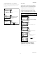
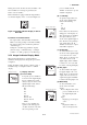
1. Call up the “HART output” display. [1.Device
setup → 4.Detailed setup → 3.Output condition →
2.HART output]
2. Select “4. Burst option”. Select a set of data to be
sent.
3. Return to “HART output” display and select “3.
Burst mode”. Select “On” to start the burst option.
Press SEND[F2] to send the setting. To release the
burst mode, select “Off” in this display.
If the transmitter is equipped with the integral indica-
tor, the LCD displays “B.M.”
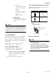
3.5.10 Multi Drop
“Multi dropping” transmitters refers to the connection
of several transmitters to a single communication
transmission line. Up to 15 transmitters can be con-
nected when set in the multidrop mode. To activate
multi drop communication, the transmitter address
must be changed to a number from 1 to 15. This
change deactivates the 4 to 20 mA analog output,
sending it to 4mA . The alarm current is also disabled.
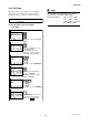
● Setting of Multi drop
Call up the “HART output” display. [1.Device
setup → 4.Detailed setup → 3.Output condition →
2.HART output]
Select “1. Poll addr” and set the polling address.(a
number from 1 to 15).
Press SEND[F2] to send the setting.
If the transmitter is equipped with the integral indica-
tor, the LCD displays “M.D.” and "F.O."
NOTE
1. When the identical address is set for two or
more transmitters in multidrop mode, commu-
nication with these transmitters is disabled.
2. Multi drop mode and Burst mode should not
be operated together at the same time.
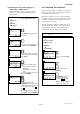
● Releasing the Multidrop mode
First, call up the “HART output” display. [1.Device
setup → 4.Detailed setup → 3.Output condition →
2.HART output]
Select “1. Poll addr” and set the polling address to
“0”. Press SEND[F2].
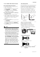
3.5.11 Sensor Matching Function
This function is available only when optional specifica-
tion /CM1 is specified with YTA310 or YTA320.
Siginificant temperature measurement accuracy
improvement can be obtained using a temperature
sensor that is matched to a transmitter. This matching
process entails teaching the transmitter the relationship
between resistance and temperature for a specific RTD
sensor. This relationship, approximated by the
Callender-van Dusen equation, is described as follow-
ing :
Rt = R0 {1 + α (1+0.01δ ) t - αδ / 10
4
t
2
- αβ / 10
8
(t -100 ) t
3
}
where : Rt = Resistance (ohms) at
Tempearature t (
o
C)
R0 = Sensor -specific constant
(Resistance at t=0
o
C)
α (alpha) = Sensor-specific constant
δ (delta) = Sensor-specific constant
β (beta) = Sensor-specific constant
(0 at t>0
o
C)
Although the sensor curve is standardized, the exact
values for R0, α, δ and β are specific to each RTD
sensor and are obtained by testing each individual
sensor at various temperatures. These constants are
known as Callender-van Dusen constants.
Generally, the constants R0, A, B, and C are also used
as the characteristic coefficients of the RTD instead of
R0, α, δ and β. These are derived from IEC Standard
Curve and the relationship is described as followings ;
Rt = R0 {1 + At - Bt
2
+ C (t -100) t
3
}
where : Rt = Resistance (ohms) at
Tempearature t (
o
C)
R0 = Sensor-specific constant
(Resistance at t=0
o
C)
A = Sensor-specific constant
B = Sensor-specific constant
C =Sensor-specific constant
(0 at t > 0
o
C)
These two equations are equivalent. A model YTA
can cope with either case as above-mentioned.