
User guide

3. OPERATION
IM 01C50T01-01E
3-14
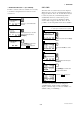
3.5.5.3 Software Write Protect Function
● To activate write protect function
1. Press Hot key and select “2. Wrt protect menu”.
2. Select “3.New password”.
3. Enter up to 8 alphanumeric string from key-pads.
Press ENTER[F4].
4. Re enter the strings and press ENTER[F4].
5. Press OK[F4] to set the password. The status is
changed to “Write protect YES”.
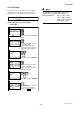
● To change the password or to release the
write protect mode
1. Press Hot key and select “2. Wrt protect menu” .
2. Select “2. Enable wrt 10 min”. Enter the password.
By this operation, the write protection is released
for 10 minutes. It is possible to change the
paramters.
3. Select “3.New password”.
4. To change the password, enter new password and
press ENTER[F4].
To release the write protect mode, enter 8 spaces in
the new password field and press ENTER[F4].
5. Press OK[F4] to set the new password or to release
the write protect mode.
NOTE
1. “Enable Wrt 10 min” releases write protect
status for 10 minutes. While write protect is
released, enter a new password in the “New
Password” field. It will not be possible to set a
new password after 10 minutes have elapsed.
2. “Joker Password” and “Software Seal”
When you foget the password that has been
registered, it is possible to release the mode
for 10 minutes by using a joker password.
Enter YOKOGAWA to release write protect
status for 10 minutes. If this joker password is
used, the status shown in the parameter
“Software seal” is changed from “Keep” to
“Break”. Press Hot key and select “2. Wrt
Protect menu” . Current status is shown in “4.
Software seal”. This status will be returned
from “Break” to “Keep” by registering a new
password.
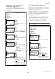
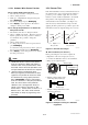
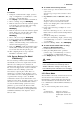
3.5.6 Sensor Trim
Each YTA transmitter is factory-characterized based on
the standard sensor curve, and uses this information to
produce a process variable output. The sensor trim
function is used to make an adjustment to the internal
interpretation of the input signal and the factory
characterization in the transmitter. (See Figure 3.4)
Since the factory characterization is kept even after
applying the trim operation, it is possible to ignore the
trim function when the original settings are recovered.
Input
ZERO ZERO
GAIN
Input
One point trim Two point trim
Output
Output
F0307.EPS
Figure 3.4 Trim function images
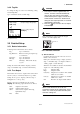
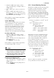
● The Procedures (For Sensor 1)
Before performing the sensor trim, complete the
configuration of the sensor input. (See 3.4.1-2)
1. Connect the calibration device to the transmitter.
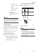
a. Wiring of power supply and output
b. Example of wiring of thermocouple
or DC voltage input (1-input type)
F0305.EPS
+ Output signal
–
Load resistance
DC voltage generator or
thermocouple
Voltmeter
1
2
3
4
5
c. Example of wiring of thermometer resistor
4-wire type (1-input type)
Variable resistor or
thermometer resistor
1
2
3
4
5
(+)
(A)
(B)
(B)
(A)
(–)
Figure 3.5 Example of wiring for calibration
equipment