
User guide

3. OPERATION
IM 01C50T01-01E
3-7
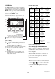
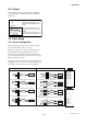
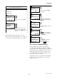
YTA :
PV is Snsr1
SV is Term
TV is Not used
4V is Not used
Pressing
'OK' to change
them.
HELP SAVE ABORT OK
1
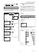
YTA :
PV is
Snsr1
Snsr1
Snsr1-Term
Term
HELP SEND ABORT ENTER
2
YTA :
PV is Snsr1
SV is Term
TV is Not used
4V is Not used
Pressing 'OK' will
send them.
HELP SEND ABORT OK
4
The display in the left shows the
current setting of the map.
Press OK[F4].
Calling up the “Variable map”
display.
Scroll with the up/down key until
the designated sensor type is high-
lightened. Press ENTER[F4] to
set the type. The selection is as
follows.
[For YTA110, YTA310]
Sensor1
Sensor1 - Terminal Temperature
Terminal Temperature
[For YTA320]
Above plus ;
Sensor2
Sensor2 - Terminal Temperature
Diff : Sensor2-Sensor1 or
Sensor1-Sensor2
Average : (Sensor1+Sensor2)/2
Follow the same procedures for
SV, TV and 4V. When you want to
leave the setting as it is, just press
ENTER [F4] to move to the next
variable display. Pressing
ABORT[F3] will cancel all the
previous procedures for mapping.
Press OK[F4] to send the new
setting to the transmitter.
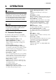
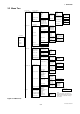
1. Device setup
1. Process Variables
2. Variable setting
1. Variable map
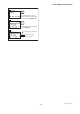
YTA :
SV is
Not used
Snsr1
Snsr1-Term
Term
Not used
HELP SEND ABORT ENTER
3
NOTE
Sensor type “Non-sntandard 1” “Non-standard 2”
are always shown, but cannot be used unless a
necessary function is pre-installed in the trans-
mitters upon shipment.
NOTE
1. When SV, TV or 4V are not required, it is
recommended to leave them as “Not used”
to improve the performance.
2. Each process variable, for example “Sensor1”,
can be assigned to only one variable. If
“Sensor1” is already set as PV, it cannot be
set as SV, TV or 4V simultaneously.
4. When “Diff”, “Avg”, “Snsr1-Trem”, or “Snsr2-
Trem” are selected, the sensor types to be
set for Sensor1 and Sensor2 should be
selected from any one of the following three
groups; Temperature sensor(T/C and RTD),
DC voltage or resistance. The combination(for
example, temperature sensor and DC voltage
input) would cause an incorrect computation
due to the different unit system and is not
allowed.
5. When “Snsr1-Trem” or “Snsr2-Trem” are
selected, DC voltage and resistance input
should not be set for Sensor1 or Sensor2.