User’s Manual YTA series Temperature Transmitter (HART Protocol) IM 01C50T01-01E IM 01C50T01-01E 5th Edition Yokogawa Electric Corporation
Blank Page
CONTENTS CONTENTS 1. INTRODUCTION .......................................................................................... 1-1 Regarding This Manual ................................................................................. 1-1 For Safe Use of Product ............................................................................... 1-2 Warranty ........................................................................................................ 1-2 ATEX Documentation.............................
CONTENTS APPENDIX A. SAFETY INSTRUMENTED SYSTEMS INSTALLATION ......... A-1 A.1 Scope and Purpose ............................................................................ A-1 A.2 Using the YTA for an SIS Application ................................................ A-1 A.2.1 Safety Accuracy ........................................................................... A-1 A.2.2 Diagnostic Response Time .......................................................... A-1 A.2.3 Setup ..............................
1. INTRODUCTION 1. INTRODUCTION Thank you for purchasing the YTA series Temperature Transmitter. WARNING Indicates a potentially hazardous situation which, if not avoided, could result in death or serious injury. The YTA series Temperature Transmitters are correctly calibrated at the factory before shipment. To ensure correct and efficient use of the instrument, please read this manual thoroughly and fully understand how to operate the instrument before operating it.
1. INTRODUCTION 䊏 For Safe Use of Product 䊏 Warranty For the protection and safety of the operator and the instrument or the system including the instrument, please be sure to follow the instructions on safety described in this manual when handling this instrument. In case the instrument is handled in contradiction to these instructions, Yokogawa does not guarantee safety. Please give your attention to the followings.
1. INTRODUCTION 䊏 ATEX Documentation SF This procedure is only applicable to the countries in European Union. Kaikkien ATEX Ex -tyyppisten tuotteiden käyttöhjeet ovat saatavilla englannin-, saksan- ja ranskankielisinä. Mikäli tarvitsette Ex -tyyppisten tuotteiden ohjeita omalla paikallisella kielellännne, ottakaa yhteyttä lähimpään Yokogawa-toimistoon tai -edustajaan. GB All instruction manuals for ATEX Ex related products are available in English, German and French.
1. INTRODUCTION 1.1 Matching of DD and Instruments To setup the YTA via HART handheld communicator, it is necessary that the correct version of DD(Device Description) is installed in the communicator. The matching of the instrument and the DD in the communicator can be checked by the following procedures. If the correct DD is not installed in your communicator, contact your nearest official programming site for HART Communicator and ask for an update.
2. HART COMMUNICATOR OPERATION 2. HART COMMUNICATOR OPERATION Maximum twisted-pair length; 10,000 ft (3,048 m) Maximum multiple twisted-pair length; 5,000 ft (1,524 m) Use the following formula to determine cable length for a specific application; 2.1 Conditions of Communication Line 2.1.
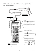
2. HART COMMUNICATOR OPERATION 2.2 Basic Operation of the HART Communicator (Model 275) 2.2.1 Keys and Functions Communication Cable LCD (Liquid crystal display) (21 characters×8 lines) Function keys Functions of the keys are indicated on the display. Pressing (HOME) when the display is as shown changes the display to “Online” menu. (See 2.2.2 “Display”.) YTA : Online 1 Device setup 2 PV 0.00 degC 3 PV AO 4.001 mA 4 PV LRV 0.00 degC 5 PV URV 100.
2. HART COMMUNICATOR OPERATION 2.2.2 Display Function Key Labels The HART communicator searches for transmitter on the 4 to 20 mA loop when it is turned on. When the HART communicator is connected to the transmitter, “Online” menu (Top menu) is started automatically and the following display appears. If no transmitter is found, you select “Online” menu. Manufacturer’s transmitter type Tag (8 Characters) YTA :YOKOGAWA Online 1 Device setup 2 PV 0.00 degC 3 PV AO 4.001 mA 4 PV LRV 0.
2. HART COMMUNICATOR OPERATION • To return to the previous display, press the * If ABORT , ESC desired function key. and EXIT 2.2.4 Entering, Setting and Sending Data key. are displayed, press the The data input using the keys are stored in the HART communicator by pressing ENTER (F4). Then, by pressing SEND (F2), the data is sent to the transmitter. Note that the data is not stored in the transmitter if SEND (F2) is not pressed.
2. HART COMMUNICATOR OPERATION 5 Display Operation YTA :YOKOGAWA Tag YOKOGAWA FIC-1A (ENTER) HELP DEL ESC ENTER After entering the data, set the HART communicator with the data entered by pressing ENTER (F4). 6 YTA :YOKOGAWA Basic setup 1 Tag FIC-1A 2 PV Unit&Damp 3 Range values 4 Snsr 1 config 5 Snsr 2 config HELP SEND HOME ENTER (SEND) Send the data to the transmitter by pressing SEND (F2).
3. OPERATION 3. OPERATION • Tag No., Message, Descriptor (→ 3.4.6 , 3.5.1) Setting data in Tag, Message, and Descriptor parameters. • Test Output (→ 3.5.2) Make the transmitter output a fixed current from -2.5 through 110 % in 0.1% increments for loop checks. • Sensor Burnout (→ 3.5.3) Configure the current output value in sensor failure. Selectable from High, Low and User setting value. • Integral Indicator Display Mode (→ 3.5.4) To change items to be displayed on the Integral Indicator.
3. OPERATION Table 3.1 Parameters list Item Sensor1 Configuration Sensor2 Configuration (YTA320 only) Note 1: Note 2: Page Tag number, up to 8 characters 3-11 Tag Ex Extension of Tag, up to 8 characters 3-11 Descriptor Up to 16 characters 3-11 Message Up to 32 characters 3-11 Date mm/dd/yy 3-11 Sensor1(2) snsr s/n To describe a serial number of sensor.
3. OPERATION Item Output Display (Note 3) Monitoring Maintenance Note 3: Page 3-11 Show the current setting of the output direction in CPU failure which is set by hardware switch on a CPU assembly. Select a set of data to be continuously sent; (1)PV, (2)output in % range & current, (3)PV and output in current. 3-11 Burst mode Enable/disable the burst mode. 3-16 Multi-drop mode Poll addr Setting the polling address (0 to 15).
3. OPERATION 3.2 Menu Tree (Device setup) 1.Process variables (Process Variables) 1.Variable view 1.PV 2.PV % rnge 3.PV AO 4.SV 5.TV 6.4V 7.Term 2.Diff direction 1.PV is 2.SV is 3.TV is 4.4V is 1.PV Unit 2.PV Damp 3.PV damp point 1.PV Unit&Damp 1.SV Unit 2.SV Damp 2.SV Unit&Damp 2.Variable setting 3.Max/Min log 1.Variable map 3.Unit&Damp 1.PV max/min log 2.SV max/min log 3.TV max/min log 4.4V max/min log 5.Term max/min log 6.Max/Min log Clear 3.TV Unit&Damp 1.TV Unit 2.TV Damp 4.
3. OPERATION 3.3 Review Before starting operation, review all the configuration of the transmitter to confirm that it meets the current application. 1. Device setup Call up “Review” display. Parameters are grouped by type and listed in review display of each group. 5. Review YTA : Review 1. Sensor 1 Review 2. Term temp Review 3. Out & Meter Review ENTER 4. Device Review HELP SAVE HOME Call up each review display, and scroll through the list to check each variable.
3. OPERATION 3 Example: To set Pt100, 4-wire sensor as “Sensor1” input. Also set a unit for Sensor1 as “°C”. YTA : Snsr 1 config 1. Snsr1 Type 2. Snsr1 Wire 3. Snsr1 unit 3 Wire deg C Call up the “Snsr 1 config” display. 1. Device setup HELP HOME ENTER ESC ENTER 3. Basic setup 4 4. Snsr 1 config YTA : Snsr1 Wire 3 Wire 2 Wire 3 Wire 4 Wire 1 YTA : Snsr 1 config 1. Snsr1 Type 2. Snsr1 Wire 3. Snsr1 unit HELP SAVE HOME Enter “2” to call up “Snsr1 Wire” setting display.
3. OPERATION 1. Device setup NOTE Calling up the “Variable map” display. 1. Process Variables Sensor type “Non-sntandard 1” “Non-standard 2” are always shown, but cannot be used unless a necessary function is pre-installed in the transmitters upon shipment. 2. Variable setting 1. Variable map 1 YTA : PV is Snsr1 SV is Term TV is Not used 4V is Not used Pressing 'OK' to change them. HELP SAVE ABORT OK NOTE The display in the left shows the current setting of the map. Press OK[F4]. 1.
3. OPERATION 3.4.3 Unit — Differential Direction — (For YTA320) If “Diff” is selected as Process variables, it is necessary to set which is designated; Sensor1-Sensor2 or Sensor2-Sensor1. The unit for PV is set at the factory before shipment. When Sensor1(or Sensor2) or Terminal temperature is mapped as PV, SV, TV or 4V, the unit that is selected for Sensor1(orSensor2) or Terminal temperature is automatically referred as a unit for these process variables. (See 3.4.
3. OPERATION 3.4.4 PV Range NOTE The range for PV corresponding to the 4 to 20mA output signal is set at the factory before shipment. Following are the procedures to change the range. It is possible to set LRV>URV. This setting reverses the 4 to 20 mA output signal. Setting Conditions: LSL <= LRV <= USL LSL <= URV <= USL |URV – LRV| >= Recom mended Min. span Example: To change the range from “0 to 100 °C” to “50 to 200 °C”. (1) Changing the range with Keypad – LRV, URV – 1 YTA Hot 1. 2.
3. OPERATION 3.4.5 Damping Time Constant (2) Changing the range while applying an actual input – Apply values – This feature allows the lower and upper range values to be setup automatically with the actual input applied. 1. Device setup Setting the response time of each Process Variable to make it vary slowly with a rapid change in input. Set the value from 0 to 99 seconds.
3. OPERATION 3.4.6 Tag No. CAUTION To change the Tag, see section 2.2.4 “Entering, setting and Sending Data”. 1. Test output is held for approximately 10 minutes, and then released automatically after the time has elapsed. If the HART communicator power supply is turned off or communication connector is disconnected during the test output operation, it is held for approximately 10 minutes. key to release the test output 2. Press the immediately. Up to 8 characters can be set with “Tag”.
3. OPERATION During sensor burn out time, the Sensor1 failure or the Sensor2 failure error message is generated. (See Section 3.6.1 for details.) process variable is lit. If “Inhibit” is selected, no process variable is displayed. If the transmitter is equipped with the integral indicator, the LCD displays “Abn.” as shown in Figure 3.2. (b) % /mA Disp To Specify output value to be shown on the digital display.
3. OPERATION 3.5.5.2 Hardware Write Protect Function Process, Type: Display Process Variable name and Sensor Type in turn. Type, Wire: Display Sensor Type and the number of wires in turn Inhibit: Display none. Hardware write protect function is set up by Switch (SW2) on the CPU assembly. Pin position of SW2 Write Protect Status WP Y No SW2 N WP 2) Disp Update Update period of the display is selected from Normal, Fast and Slow.
3. OPERATION 3.5.5.3 Software Write Protect Function 3.5.6 Sensor Trim ● 1. 2. 3. Each YTA transmitter is factory-characterized based on the standard sensor curve, and uses this information to produce a process variable output. The sensor trim function is used to make an adjustment to the internal interpretation of the input signal and the factory characterization in the transmitter. (See Figure 3.4) To activate write protect function Press Hot key and select “2. Wrt protect menu”. Select “3.
3. OPERATION 2. Call up the “Snsr1 inp trim” display. [1.Device setup → 2. Diag/Service → 3.Calibration → 3.Sensor Trim → 1.Snsr 1 inp trim] 3. Select “2.Input Trimming Mode”. The following selections are offered. V.R. / ZERO&GAIN V.R. / ZERO Temp / ZERO&GAIN Temp / ZERO Select “V.R. / ZERO&GAIN” or “V.R. / ZERO” when the calibration device is DC voltage generator or Variable resistor or select “TEMP / ZERO&GAIN” or “TEMP / ZERO” when the device is Temperature sensor. 4. Enable the user trim. Select “3.
3. OPERATION ● To enable Sensor backup function 1. Set the sensor type, wire and unit for Sensor1 and 2. (See 3.4.1) Any Sensor type except “Non-connection” can be selected. 2. Map Sensor1 as PV, and Sensor2 as SV. (See 3.4.2) TV and 4V can be set to any designated value except for “Sensor1” and “Sensor2” from the selection. Sets damping time constant and unit for each process variable. 3. Set the sensor burnout type to High, Low or user setting value.
3. OPERATION 3.5.11 Sensor Matching Function 1. Call up the “HART output” display. [1.Device setup → 4.Detailed setup → 3.Output condition → 2.HART output] 2. Select “4. Burst option”. Select a set of data to be sent. 3. Return to “HART output” display and select “3. Burst mode”. Select “On” to start the burst option. Press SEND[F2] to send the setting. To release the burst mode, select “Off” in this display.
3. OPERATION ● For Setting up two sensors (For model YTA320 ) If using two sensors with a model YTA320, repeat the procedures for the Sensor2. [1. Device setup → 3. Basic setup → 5. Snsr 2 config ] NOTE 1. This function is effective only in three kinds of sensors; Pt100, Pt200 and Pt500. 2. Input relations between the sensor type and the value of R0 properly. When Pt100 is specified as an input type, the value close to 100 must be set to R0.
3. OPERATION iimmediately. Warnings are the light errors and indication of the status which is important for operation. When an error message appears, see table 3.4 “List of Errors” for details. If warning messages are set be shown, the warning status will also be shown on the HART communicator. See table 3.5 “List of Warnings” for details. Diagnostic by “Self test” 1. Device setup 2. Diag/Service 1.
3. OPERATION Table 3.4 List of Errors Indicator HART display N/A Er-01 Good Output Too Low Er-02 Output operation upon error Cause Action Input value is lower than the PV low range value. Output goes to minimum value(–2.0%). Check the LRV setting and adjust. Output Too High Input value is higher than the PV upper range value. Output goes to maximum value(105%). Check the URV setting and adjust. Er-03 Sensor1 Failure Sensor1 fails or disconnects from the terminal block.
3. OPERATION Table 3.5 List of Warnings Group(note) group1 Parameter The LRV setting is lower than the temperature range (GS guaranteed value). Check the LRV setting. LRV Too High The LRV setting is higher than the temperature range (GS guaranteed value). Check the LRV setting. URV Too Low The URV setting is lower than the temperature range (GS guaranteed value). Check the URV setting. URV Too High The URV setting is higher than the temperature range (GS guaranteed value).
3. OPERATION 3.6.2 Warnings 3. To clear the logged data for Process variables, return the “Max/Min log” display and select “Max/ Min log Clear”. Select “Execute” and press ENTER[F4]. Even after this operation, the logged data for terminal temperature shall remain. When non-fatal errors or unusual status such as invalid setting of parameters has happened, it can be detected and shown on the HART commnuicator as a warning message.
4. PARAMETERS LISTS 4. PARAMETERS LISTS Initial setting value marked with “ * ” is as of specified upon ordering. Item Up to 8 characters —* Up to 8 characters — Descriptor Up to 16 characters — Message Up to 32 characters — Date mm/dd/yy — Snsr1(2) snsr s/n 0 to 16777215 — Engineering Unit PV unit (SV,TV,4V) °C, K,°F, or °R (see note 1) °C* Range LRV/URV Set the calibration range using the keypad. Apply values Value for 4 and 20 mA signal is set with actual input applied.
4. PARAMETERS LISTS Item Display (see note 3) Output Monitoring Maintenance Display select Note 3: Initial Setting (1)PV (2)SV (3)TV (4)4V (5)PV,SV (6)PV,SV,TV (7)PV,SV,TV,4V (8)Inhibit PV %/mA Disp (1)mA (2)% (3)mA,% (4)Inhibit mA Error-No Disp Show or Inhibit Show Bar graph Show or Inhibit Show Matrix Disp (1)Process (2)Type (3)Wire (4)Process,Type (5)Type,Wire (6)Inhibit Process Fast, normal, or slow.
APPENDIX A. SAFETY INSTRUMENTED SYSTEMS INSTALLATION APPENDIX A. SAFETY INSTRUMENTED SYSTEMS INSTALLATION The calibration of the transmitter must be performed after parameters are set. WARNING The contents of this appendix are cited from exida.com safety manual on the YTA series pressure transmitters specifically observed for the safety transmitter purpose.
APPENDIX A. SAFETY INSTRUMENTED SYSTEMS INSTALLATION Table A.2.5 Proof Testing Testing method Analog Output Loop Test: Tools required Expected outcome Handheld terminal Proof Test Coverage =61% The output needs to be monitored to assure that the transmitter communicates the correct signal. Handheld terminal Proof Test Coverage =96% The output needs to be monitored to assure that the transmitter communicates the correct signal. 1.
APPENDIX A. SAFETY INSTRUMENTED SYSTEMS INSTALLATION A.2.9 Reliability Data A SIS is composed of any combination of sensor(s), logic solver(s), and final element(s). A detailed Failure Mode, Effects, and Diagnostics Analysis (FMEDA) report is available from Yokogawa with all failure rates and failure modes.
◆ Revision Record ● Manual No. : IM 01C50T01-01E ● Title : YTA series Temperature Transmitter (HART Protocol) Edition Date Page Revised item 1st Sep. 1998 — New Publication 2nd Jan. 1999 — Error Correction 3rd Jun. 1999 3-3, 3-5, 4-1 3-23 Add parameters related to Sensor matching function. Add “3.5.11 Sensor Matching Function”. 4th July 2000 Cover CONTENTS 1-3 3-3, 3-4 3-5 3-9 3-18 3-23 3-28 4-1, 4-2 Add style code Add “1.1 Matching of DD and instruments”, “3.5.12 CJC Selection” Add “1.
Blank Page