
Instruction Manual

IM 01C50T03-01E
5-1
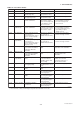
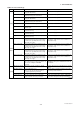
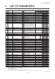
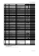
5. LIST OF PARAMETERS
5. LIST OF PARAMETERS
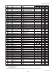
NO. Parameter name Content R/W Remarks
Applicable model
UPLOAD DATA
110 310 320 SET ALL
Data initial value
YTA110 YTA310 YTA320
01 MODEL Model R
02 TAG No. Tag number R
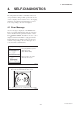
03 SELF CHECK Self-diagnostics R
A VARIABLE Variable R
A10 PV Primary variable R Unit specified in B11
A11 mA of RANGE Output in mA R 3.6 to 21.6 mA
A12 % of RANGE Output in % R -2 to 110%
A20 SV Secondary variable R Unit specified in B21
A30 TV Tertiary variable R Unit specified in B31
A40 4V Fourth variable R Unit specified in B41
A50 TERM Terminal temperature R Unit specified in B51
A60 SELF CHECK Self-diagnostics R
GOOD, ERROR, Lower Output, Upper Output,
Sensor1 Failure, Sensor2 Failure, S1 Signal
Error, S2 Signal Error, Lower Amb TEMP,
Upper Amb TEMP, Sns Backup Start, Illegal PV
MAP, Term Sns Failure, EEPROM Failure, CPU
Failure, AD Conv Failure, Reverse Cal Fail
B SET VAR CON. Set process variable condition R
B05 SET DIFF Set differential direction W Sensor1-Sensor2, Sensor2-Sensor1
B10 PV is PV mapping W Sensor1, Sensor2
*
, DIFFERENCE
*
,
AVERAGE
*
, Sensor1-Term, Sensor2-Term
*
,
Terminal Temp
(* item can be selected only with YTA320)
B11 PV UNIT PV engineering unit W degC, kelvin, degF
*4
, degR
*4
B12 PV DAMPING PV damping time constant W 0 to 99 seconds
B13 PV DMP POINT PV damping holding point W 0 to 99%
B20 SV is SV mapping W Sensor1, Sensor2
*
, DIFFERENCE
*
,
AVERAGE
*
, Sensor1-Term, Sensor2-Term
*
,
Terminal Temp Not Used
(* item can be selected only with YTA320)
B21 SV UNIT SV engineering unit W degC, kelvin, degF
*4
, degR
*4
B22 SV DAMPING SV damping time constant W 0 to 99 seconds
B30 TV is TV mapping W Same as B20
B31 TV UNIT TV engineering unit W degC, kelvin, degF
*4
, degR
*4
B32 TV DAMPING TV damping time constant W 0 to 99 seconds
B40 4V is 4V mapping W Same as B20
B41 4V UNIT 4V engineering unit W degC, kelvin, degF
*4
, degR
*4
B42 4V DAMPING 4V damping time constant W 0 to 99 seconds
B51 TERM UNIT Terminal temperature unit W degC, kelvin, degF
*4
, degR
*4
B60 SELF CHECK Self-diagnostics R Same as A60
C SET TAG Set Tag number R
C10 TAG NO. Tag number W 16 alphanumeric characters
C60 SELF CHECK Self-diagnostics R Same as A60
D SET SENSOR1 Set Sensor1 R
D10
SENSOR1 TYPE
Sensor1 sensor type W TYPE B, E, J, K, L, N, R, S, T, U, W3, W5,
Pt100, Pt200, Pt500, JPt100, Ni120, Cu,
ohm, mV, Non Connection
D20 SENSOR1 WIRE Sensor1 wire connection W 2 WIRE, 3 WIRE, 4 WIRE
D40 SENSOR1 Sensor1 input value R Unit specified in D20
D41 SENSOR1 UNIT Sensor1 engineering unit W degC, kelvin, degF
*4
, degR
*4
D50 SNSR1 MATCH Sensor1 RTD sensor matching W DISABLE, ENABLE
D51 SNSR1 R0 Sensor1-specific constant (R0) W
D52 SNSR1 A IEC co-efficient W
D53 SNSR1 B IEC co-efficient W
D54 SNSR1 C IEC co-efficient W
D55 SNSR1 ALPHA Callendar-Van-Dusen co-efficient A W
D56 SNSR1 DELTA Callendar-Van-Dusen co-efficient B W
D57 SNSR1 BETA Callendar-Van-Dusen co-efficient C W
D60 SELF CHECK Self-diagnostics R Same as A60
YTA110 YTA310 YTA320
Specified upon order
GOOD
Operation
Operation
Operation
Operation
Operation
Operation
Operation
GOOD
Sensor1-Sensor2
Sensor1
degC
2 seconds
2 %
Not Used
degC
2 seconds
Not Used
degC
2 seconds
Not Used
degC
2 seconds
degC
GOOD
Specified upon order
GOOD
Pt100
3 WIRE
Operation
degC
DISABLE
+100
+3.9083 E-3
-5.7749 E-7
-4.183 E-12
+3.8505 E-3
+1.4998 E0
+1.0862 E-1
GOOD
● ● ●
● ● ●
● ● ●
● ● ●
● ● ●
● ● ●
● ● ●
● ● ●
● ● ●
● ● ●
● ● ●
● ● ●
● ● ●
● ● ●
● ● ● ● ●
● ● ● ● ●
● ● ● ● ●
● ● ● ● ●
● ● ● ● ●
● ● ● ● ●
● ● ● ● ●
● ● ● ● ●
● ● ● ● ●
● ● ● ● ●
● ● ● ● ●
● ● ● ● ●
● ● ● ● ●
● ● ● ● ●
● ● ●
● ● ●
● ● ● ●
● ● ●
● ● ●
● ● ● ● ●
● ● ● ● ●
● ● ●
● ● ● ● ●
● ●
● ●
● ●
● ●
● ●
● ●
● ●
● ●
● ● ●
*1: ◆ indicates parameters which may be displayed depending on the setting for other parameters. ● indicates parameters available on the model with optional code /CM1.
*2: RW: R = Read only, W = Read & Write
*3: Indicates the parameter selected by H30: UPLOAD SELCT.
SET = SET PRAM ONLY parameters
ALL = ALL PRAM parameters
*4: degF and degR can be selected only when optional code /D2 is specified.
*5: This parameter will not be printed at PRINTOUT upon UPLOAD/DOWNLOAD, although the parameter itself is UPLOADED/DOWNLOADED.
*1 *2
*3
◆
◆
◆
◆
◆
◆
◆
◆
◆
◆
◆
◆
●
●
●
●
●
●
●
●
Sensor2
*5