User’s Manual YTA Series Temperature Transmitter (BRAIN Protocol) IM 01C50T03-01E IM 01C50T03-01E Yokogawa Electric Corporation 5th Edition
CONTENTS CONTENTS 1. INTRODUCTION .......................................................................................... 1-1 ■ ■ ■ ■ 2. Regarding This Manual ............................................................................. 1-1 For Safe Use of Product ........................................................................... 1-2 Warranty .................................................................................................... 1-2 ATEX Documentation ...........................
CONTENTS APPENDIX A. OPERATION OF BRAIN TERMINAL BT200 ............................. A-1 A.1 Operation Key Arrangement ............................................................... A-1 A.2 Function of Operation Keys ................................................................ A-2 A.2.1 Entry of Alphanumeric Characters ............................................... A-2 A.2.2 Function Keys ............................................................................... A-3 A.3 Calling of Menu Address .
1. INTRODUCTION 1. INTRODUCTION Thank you for purchasing the YTA series Temperature Transmitter. • The following safety symbol marks are used in this Manual: The YTA temperature transmitter is fully factory-tested according to the specifications indicated on your order.
1. INTRODUCTION 䊏 For Safe Use of Product 䊏 Warranty For the protection and safety of the operator and the instrument or the system including the instrument, please be sure to follow the instructions on safety described in this manual when handling this instrument. In case the instrument is handled in contradiction to these instructions, Yokogawa does not guarantee safety. Please give your attention to the followings.
1. INTRODUCTION 䊏 ATEX Documentation This procedure is only applicable to the countries in European Union. GB All instruction manuals for ATEX Ex related products are available in English, German and French. Should you require Ex related instructions in your local language, you are to contact your nearest Yokogawa office or representative. DK Alle brugervejledninger for produkter relateret til ATEX Ex er tilgængelige på engelsk, tysk og fransk.
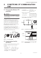
2. CONDITIONS OF COMMUNICATION LINE 2. CONDITIONS OF COMMUNICATION LINE Load impedance : 3.3 mH or less Communication distance: 2 km (1.25 mile), when CEV cable is used Distance from the power line: Output signal line : 15 cm (5.9 inch) or more (do not use parallel wiring) Input signal line : 100 cm (39.8 inch) or more (do not use parallel wiring) Input impedance of receiver connected to receiving resistor: 10 kΩ more (at 2.4 kHz) 2.
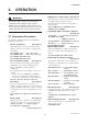
3. OPERATION 3. OPERATION IMPORTANT Do not turn off the power to the transmitter immediately after setting the data using the BT200. If the transmitter is turned off less than 30 seconds after parameters have been set, the setting data will not be stored in the transmitter. • Damping time constant setting See Page 3-6 Setting the response time of the transmitter smooths the output with rapid changes in input. The damping time constant can be set between 1 and 99 seconds.
3. OPERATION • Sensor Backup Function (YTA320 only) See Page 3-10 Configure the transmitter to automatically transfer the input from Sensor1 to Sensor2 when Sensor1 fails. H20: SNSR BACKUP, H21: RETURN SNS1 • Copy the Setting Data to the BT200 See Page 3-11 Copy the setting data of one temperature transmitter to another via the BT200.
3. OPERATION Menu tree for YTA110 & YTA310 SET HOME A:VARIABLE B:SET VAR CON. ADJ A10:PV A11:mA of RANGE A12:% of RANGE A20:SV A30:TV A40:4V A50: TERM A60:SELF CHECK C:SET TAG C10:TAG NO.
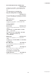
3. OPERATION 3.2 Setting Parameters 3.2.1 Sensor Configuration When the sensor type or the number of wire connections changes, the following parameters must be reset. Sensor type setting; D10: SENSOR1 TYPE, E10: SENSOR2 TYPE Wire connections setting; D20: SENSOR1 WIRE, E20: SENSOR2 WIRE Figure 3.1 diagram shows the wire connections to the input terminals of the transmitter and sensor type selections for the parameters in each connection case.
3. OPERATION AVERAGE <1> PARAM D10:SENSOR1 TYPE Pt200 (IEC751) D20:SENSOR WIRE 3 WIRE D40:SENSOR1 TEMP 23.56 degC DATA DIAG PRNT ESC 1. Select D: SET SENSOR1 to go to the screen (1). 2. Select “D10” and press [ENTER] to go to the screen (2). <2> SET D10:SENSOR1 TYPE Pt200 (IEC751) > > > ESC 3. Select “Pt100” and press [ENTER] twice. 4. Check that “Pt100” has been set and press [OK].
3. OPERATION 3.2.3 Unit Setting 3.2.5 Setting Damping Time Constant B11: PV UNIT, B21: SV UNIT, B31: TV UNIT, B41: 4V B12: PV DAMPING, B22: SV DAMPING, UNIT B32: TV DAMPING, B42: 4V DAMPING Select the engineering unit for the process variables assigned as PV, SV, TV, and 4V from degree C, Kelvin, degree F* and degree R*. When mV or ohm is specified as an input type, the unit is automatically set to mV or ohms.
3. OPERATION Memo IMPORTANT O10: MEMO1, O20: MEMO2 Up to sixteen alphanumeric characters can be entered. • Manual mode output is held for approximately 10 minutes and then released automatically after the time has elapsed. Even if the BT200 power supply is turned off or the communication connector is disconnected during the test, it is held for approximately 10 minutes. • To release the test output immediately, set “AUTOMATIC MODE” at G10 as seen in the figure above or turn off the transmitter.
3. OPERATION mA % mA, % : Displays output value in mA : Displays output value in % : Displays output value in mA and % alternately : The output value is not displayed INHIBIT FAST NORMAL SLOW : 1/2 of the normal cycle speed : Normal cycle speed : 1.5 times of the normal cycle speed NOTE (c) Display sensor type/number of wire connections When operating under –10°C(14°F), the display response time may be reduced. In such a case, set the display cycle speed to “NORMAL” or “SLOW.
3. OPERATION (f) Display error code M55: Err-NO DISP If an error occurs, the error code is displayed on the LCD indicator. SHOW INHIBIT : Error code is displayed : Error code is not displayed ● Example of LCD display cycle The example of the LCD indicator is based on the following settings. Assumed current status and parameter settings A10: PV = 50.0 degC A11: mA of RANGE = 12.00 mA A20: SV = 25.
3. OPERATION 3.2.9 Burn Out Function (a) Sensor burn out Configure the burn out mode in the case of sensor failure or disconnection. When the sensor failure is detected, the transmitter will output one of the following values. Displays "Abn." Displays "OUT." F0308.EPS Figure 3.2 Integral Indicator Display in Sensor Burn Out F40: BURN OUT (b) Confirming the output direction if Hardware error occurs Select from the followings: LOW HIGH USER mA USER % OFF : Outputs 3.6 mA (-2.5%) : Outputs 21.
3. OPERATION SET PRAM ONLY : Uploads the parameters with respect to the operation settings such as LRV and the sensor type. ALL PRAM : Uploads the all parameters. See the parameter list at the end of this manual for classification of the operation setting parameter groups and the parameter group unique to the equipment. See also the BT200 instruction manual, IM 1C0A11-01E, for the setting procedure.
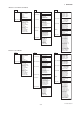
3. OPERATION Pin position of SW2 a. Wiring of power supply and output Write Protect Status WP + Output signal Y No SW2 N – Load resistance WP Y Yes SW2 N Voltmeter b. Example of wiring of thermocouple or DC voltage input (1-input type) SW1 Burnout output direction upon hardware failure 1 2 3 4 5 SW2 Hardware Write Protect (+) (–) DC voltage generator or thermocouple c. Example of wiring of thermometer resistor 4-wire type (1-input type) CPU Assembly 1 2 3 4 5 F0355.EPS Figure 3.
3. OPERATION Table 3.1 Zero and Gain point value for Sensor trim Setting value Zero-point Gain-point Sensor type TC RTD USER CAL IGNORE : Ignore user trim value and return to the factory set value. USER CAL ACT : Use user trim value.
3. OPERATION USER CAL IGNORE : Ignore user trim value and return to the factory set value. USER CAL ACT : Use user trim value. NOTE Regardless of restarting the transmitter, the “USER CAL ACT” is always set and the user trim value is used as the input signal unless it is cleared by “USER CAL CLEAR.” 3.2.16 CJC Selection For thermocouple input, terminal temperature measured by an internal sensor is used for Cold Junction Compensation function.
4. SELF-DIAGNOSTICS 4. SELF-DIAGNOSTICS The temperature transmitter continually monitors its own performance during normal operation. If an error occurs, it displays and records the error to the logging parameters, and with the integral indicator, an error code corresponding to the error is displayed. 4.1 Error Message An error message is displayed on the BT200 when there is a problem with functions. The error message can be checked with the parameter number of each item ■60:SELF CHECK.
4. SELF-DIAGNOSTICS Table 4.1 List of Error Codes Indicator BT200 display Cause Output operation upon error Action N/A GOOD Er-01 Output Too Low Input value is lower than the PV low range value. Outputs goes to minimum value. (3.68 mA, –2.0%) Check the LRV and adjust. Er-02 Output Too High Input value is higher than the PV Upper range value. Outputs goes maximum value. (20.8 mA, 105%) Check the URV and adjust. Er-03 Sensor1 Failure Sensor1 fails or disconnects from the terminal box.
4. SELF-DIAGNOSTICS 4.2 Warning ● Example: Displaying “Setting” and “Special” warning 1. Set “3FFC0108” in the Data to set column for F combination in the table above. SET H50:WARNING ENBL 00000000 3FFC0108 1) Warning and contents The YTA series has a warning display function. DEL The warning display function displays a warning when there is an incorrect use status such that a setting is out of the specified range.
4. SELF-DIAGNOSTICS Table 4.2 List of warnings Class Setting Parameter Status Countermeasure LRV Too Low The LRV setting is lower than the temperature range (GS stated value). Check the LRV setting. LRV Too High The LRV setting is higher than the temperature range (GS stated value). Check the LRV setting. URV Too Low The URV setting is lower than the temperature range (GS stated value). Check the LRV setting.
4. SELF-DIAGNOSTICS 4.3 Logging Function The YTA series has the capability to store useful information for trouble shooting. The % value is calculated from the number of BCC errors that occurred in BRAIN communication reception frame and the number of transmissions/receptions. Turning the power off clears the data. 4.3.1 Error Log *1 Up to four error histories are stored in the transmitter memory. The transmitter records an error that continues to occur for more than 6 minutes.
5. LIST OF PARAMETERS 5. LIST OF PARAMETERS *1 NO. Data initial value *2 Parameter name Content R/W Remarks *3 Applicable model UPLOAD DATA YTA110 YTA310 YTA320 110 310 320 SET ALL ● ● ● ● ● ● ● ● ● ● ● ● Operation ● ● ● 3.6 to 21.
5. LIST OF PARAMETERS *1 *2 Content R/W Remarks Data initial value *3 Applicable model UPLOAD DATA NO.
5. LIST OF PARAMETERS *1 *2 CAL SENSOR1 Sensor1 sensor trim R SNSR1 CLR Sensor1 trim value clear W USER CAL ACT, USER CAL IGNORE, USER CAL CLEAR USER CAL ACT ● ● ● J07 IN TRIM MODE Input Sensor Trimming Mode W V.R/ZERO&GAIN, V.R/ZERO, TEMP/ZERO&GAIN, TEMP/ZERO V.
APPENDIX A. OPERATION OF BRAIN TERMINAL BT200 APPENDIX A. OPERATION OF BRAIN TERMINAL BT200 A.1 Operation Key Arrangement Figure 5.3 shows the key pad layout of the BT200. BT200 BRAIN TERMINAL MENU A:VARIABLE B:SET VAR CON. HOME SET ADJ LCD 8 lines with 21 characters each ESC Functions keys Executes the commands displayed at the bottom of the screen.
APPENDIX A. OPERATION OF BRAIN TERMINAL BT200 Entry of uppercase letters A.2 Function of Operation Keys CODE CAPS CLR ESC A.2.1 Entry of Alphanumeric Characters Numbers, codes, and letters can be entered in combinations of the alphanumeric keys and the SHIFT key. • Entry of numbers, codes, and a space (0 to 9, ., –, ) Enter these items by using the alphanumeric key. Example of Entry Entry of lowercase letters CODE caps CLR ESC Key Operation -4.3 1 F0A05.EPS -0.3 F0A02.
APPENDIX A. OPERATION OF BRAIN TERMINAL BT200 A.2.2 Function Keys The functions of the function keys vary with the commands being displayed on the display screen. MENU C:SET TAG D:SET SENEOR1 E:SET SENEOR2 F:SET OUTPUT G:FORCED OUT H:SET MODE HOME SET ADJ ESC Command ADJ Description Calls up the zero-adjustment menu. CAPS/caps Changes the uppercase/lowercase mode. CLR Clears entered data/deletes all data. COPY Prints parameters on the screen. DATA Updates parameter data.
APPENDIX A. OPERATION OF BRAIN TERMINAL BT200 A.3 Calling of Menu Address ±±WELCOME±± BRAIN TERMINAL ID: BT200 STARTUP SCREEN UTILITY 1.ID 2.SECURITY CODE 3.LANGUAGE SELECT 4.LCD CONTRAST 5.PRINTER ADJUST check connection push ENTER key UTIL ESC FEED (UTIL) INITIAL DATA SCREEN PARAM 01:MODEL YTA320 02:TAG NO. YOKOGAWA 03:SELF CHECK GOOD (ESC) OK The utility screen contains the following items. 1. BT200 ID settings 2. Security code settings 3.
APPENDIX A. OPERATION OF BRAIN TERMINAL BT200 A.3.1 Data Display with BT200 A.3.2 Data Setting with BT200 The following procedure is used to display data on the BT200 screen. The following procedure is used to change YTA data settings. ● Example: Changing C10 TAG to “FIC-la.” Display Description Display Press the key to turn on the BT200. “Please wait...” is displayed for several seconds and [Start display] is displayed.
APPENDIX A. OPERATION OF BRAIN TERMINAL BT200 [SETUP SCREEN] SET C10:TAG YOKOGAWA YOKOGAWA Set the new TAG NO. (FIC-1A) FOKOGAWA FIKOGAWA CODE CAPS CLR FICOGAWA ESC FIC-GAWA FIC-1AWA (caps) FIC-1aWA FIC-1a When you have made an entry mistake, return the cursor using the key, then reenter. [SETUP SCREEN] SET C10:TAG YOKOGAWA FIC-1a _ CODE caps Set TAG NO. and press the key. CLE ESC [CONFIRMATION SCREEN] SET C10:TAG YOKOGAWA FIC-1a This is the panel for confirming set data.
APPENDIX B. THE SENSOR MATCHING FUNCTION APPENDIX B. THE SENSOR MATCHING FUNCTION B = Sensor - Specific Constant B.1 Specifications C = Sensor - Specific Constant (0 at t > 0 C) Function: The sensor-specific constants can be programmed into the transmitter. Applicable model: YTA310 /CM1, YTA320 /CM1 RTD sensor: Pt100, Pt200, Pt500 These two equations are equivalent. A model YTA can cope with either case above-mentioned.
APPENDIX B. THE SENSOR MATCHING FUNCTION 3-11.Input beta values and press [ENTER] twice. 3-12.Press [OK]. B.2 Operations (The Sensor Matching Function) 4. Enable the Sensor Matching function: 4-1. Select D50: SNSR1 MATCH and press [ENTER]. 4-2. Select “ENABLE” and press [ENTER] twice. 4-3. Press [OK]. IMPORTANT This function is effective only in three kinds of sensors, Pt100, Pt200, and Pt500. Input relations between the sensor type and the value of R0 properly.
APPENDIX C. SAFETY INSTRUMENTED SYSTEMS INSTALLATION APPENDIX C. SAFETY INSTRUMENTED SYSTEMS INSTALLATION The calibration of the transmitter must be performed after parameters are set. WARNING The contents of this appendix are cited from exida.com safety manual on the YTA series pressure transmitters specifically observed for the safety transmitter purpose.
APPENDIX C. SAFETY INSTRUMENTED SYSTEMS INSTALLATION Table C.2.5 Proof Testing Testing method Analog Output Loop Test: Tools required Expected outcome • Handheld terminal Proof Test Coverage =61% The output needs to be monitored to assure that the transmitter communicates the correct signal. • Handheld terminal Proof Test Coverage =96% The output needs to be monitored to assure that the transmitter communicates the correct signal. 1.
APPENDIX C. SAFETY INSTRUMENTED SYSTEMS INSTALLATION C.2.9 Reliability Data SIS Safety Instrumented System – Implementation of one or more Safety Instrumented Functions. A SIS is composed of any combination of sensor(s), logic solver(s), and final element(s).
Revision Record • Manual No. : IM 01C50T03-01E • Title : YTA series Temperature Transmitter (BRAIN Protocol) Edition Date Page 1st Sep. 1998 — New Publication Revised item 2nd Jan. 1999 — Error correction 3rd June 1999 Contents B-1 to B-3 Add Appendix B The Sensor Matching Function Add Appendix B The Sensor Matching Function 4th July 2000 Cover Contents 3-3 3-16 4-3 5-2, 5-3 Add style No. Add 3.2.16 Add parameters H01 & H02 Add "3.2.