
Instruction Manual

<9. Parameter Summary>
9-7
IM 01C50E01-01EN
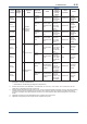
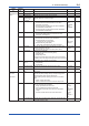
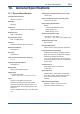
Table 9.2 Diagnostic Status Detail
Bit Diagnostic Status Detail Description
Diagnostic
status
assignment
bit
NAMUR
Diagnostic Status Detail.1
Bit31 AMP ERR Amplier failure Bit27 F
Bit30 MEMORY ERR Memory failure Bit27 F
Bit27 Firm Update ERR Firmware write error Bit27 F
Bit26 ADC ERR ADC failure Bit27 F
Bit23 SENSOR1 FAILURE Sensor 1 burnout Bit26 F
Bit22 SENSOR2 FAILURE
*1
Sensor 2 burnout Bit26 F
Bit21 TERM SNS FAILURE CJC sensor burnout Bit26 F
Bit16 CRITICAL LOWBAT
*1
Deep sleep due to low battery Bit20 M
Bit15 LOWBAT Low battery Bit19 M
Bit14 LOWBAT FOR DEEPSLEEP
*2
Deep sleep due to low battery Bit20 M
Bit11 FIRMWARE CONDITION CHECK Internal control error detection Bit21 M
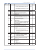
Diagnostic Status Detail.2
Bit31 SENSOR1 TEMP HI Sensor 1 temperature higher limit scale out Bit22 O
Bit30 SENSOR1 TEMP LO Sensor 1 temperature lower limit scale out Bit22 O
Bit29 SENSOR2 TEMP HI
*1
Sensor 2 temperature higher limit scale out Bit22 O
Bit28 SENSOR2 TEMP LO
*1
Sensor 2 temperature lower limit scale out Bit22 O
Bit27 AMB TEMP HI Ambient temperature higher limit scale out Bit22 O
Bit26 AMB TEMP LO Ambient temperature lower limit scale out Bit22 O
Bit23 SENSOR1 SPAN ADJ ERR Sensor 1 faulty input of span adjustment
value
Bit25 C
Bit22 SENSOR1 ZERO ADJ ERR Sensor 1 faulty input of zero adjustment value Bit25 C
Bit21 SENSOR2 SPAN ADJ ERR
*1
Sensor 2 faulty input of span adjustment
value
Bit25 C
Bit20 SENSOR2 ZERO ADJ ERR
*1
Sensor 2 faulty input of zero adjustment value Bit25 C
Bit15 AI1 O/S MODE AI1 O/S Mode Bit24 C
Bit14 AI2 O/S MODE
*1
AI2 O/S Mode Bit24 C
Bit13 AI1 SIMULATE MODE AI1 Simulate Mode Bit17 C
Bit12 AI2 SIMULATE MODE
*1
AI2 Simulate Mode Bit17 C
*1: Applicable for dual input type with detachable antenna, Amplier housing code 8 and 9.
*2: Applicable for single input type with integral antenna, Amplier housing code 7.
F0901.ai
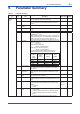
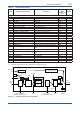
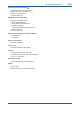
AI algorithm
Filtering
PV
AI publish
Simulate
value
Sensor
Signal
SIMULATE
Linearization
INPUT_RANGE
SENSOR_CONNECTION
Linearization
SCALE
PV_FTIME
Data Publication Period
Scale
Transducer
value
EXT_RJ_VAL
RJ.
RJ_TEMP
RJ_TYPE
BIAS
LIN_TYPE
Switch
Input
MODE.Target
NO REF
+ +
PV_TYPE
PV
PV
PV
MODE and
PV.Status handling
O/S
Auto
Man
Operator
Operator
Operator
Figure 9.1 Example schema of analog input object