
Instruction Manual
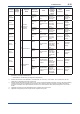
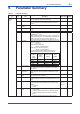
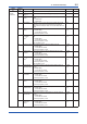
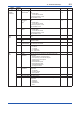
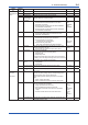

<9. Parameter Summary>
9-4
IM 01C50E01-01EN
Object
ID
Attribute
ID
Label Description Default value Handling
4.
TRANSDUCER
block
1 Tag Description Memo eld available to write anything. Transducer W
2 Model Indicates the model name of the transmitter. --- R
3 Serial Number Indicates the device number of the transmitter. --- R
4 Burn Out
*3
Hardware Burn
Out Switch
*2
Indicates the direction of the burnout switch on the integral
indicator. (Burnout Low / Burnout High)
Burn out High R
5 Wireless Status Indicates the wireless communication status
1. Indicates either the initial Idle status or Join status.
(Idle status / Join status)
2. Indicates whether Contract (Pub) has been established.
(Not established / Established)
3. Indicates whether Contract (R/W) has been established.
(Not established / Established)
1. Idle status
2. Not
established
3. Not
established
R
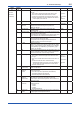
6 Display Selection Selects the LCD display
1. Indicates the display status of the AI1/AI2 PV value.
(Displayed / Not displayed)
Displayed W
7 LCD Mode Selects the LCD mode.
1. Indicates the On/Off mode. (Off / Intermittent)
2. Indicates whether or not Continue.
( Continuous Off / Continuous On)
3. Indicates the bar graph display
(Bar graph: Not displayed / Bar graph: Displayed.)
1. Off
2. Continuous
Off
3. bar graph
displayed
W
8 YTA Option Indicates the optional function supported by the device. This
cannot be changed by the user..
1. Indicates the unit system used. (SI system / Other)
Specify when
ordering
R
9 Special Cmd Special function parameter.
0. Initial value at the time of reading (None)
1. Squawk mode
2. Deep-sleep mode
To start from the deep-sleep mode, either remove and reinsert
the battery pack or use the provisioning device tool or the device
conguration tool via infrared communication.
0 W
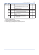
11 Power Saving
Mode
*2
Selects the power saving mode
0.Off (Disable)
1.On (Enable)
1 W
12 Mesurement Rate
*2
Indicates the measurement period of process values. 30 seconds R
14 LCD Intermittetnt
Time
*2
Set the time to turn off display on the LCD indicator.
Unit: second
60 seconds W
5.
AI1 block
6.
AI2 block
*2
1 Process Value AI1/AI2 is a temperature output object.
Indicates the primary analog value (or corresponding process
value) and status used to execute this function.
Allows updating data by specifying this for the Concentrator
object.
1. Value: AI1/AI2 output value.
2. Status: Indicates the status of the AI1/AI2 output value.
1. ---
2. ---
W
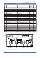
2 Mode A universal parameter to indicate the block’s operation status.
O/S, Auto, and Man can be selected.
1. Target: Species the AI1/AI2 mode.
2. Actual: Indicates the present AI1/AI2 mode.
3. Permitted: Indicates the mode that can be specied in
Target.
4. Normal: Indicates the AI1/AI2 normal status mode.
1. Target =
Auto
2. Actual =
Auto
3. Permitted
= Auto |
Manual |
OOS
4. Normal =
Auto
W
3 Concentrator OID Indicates the Concentrator object value that corresponds to the
data update of the PV value.
--- R