
Instruction Manual

<7. Setting Parameters>
7-7
IM 01C50E01-01EN
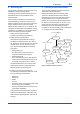
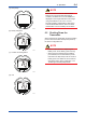
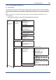
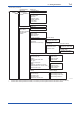
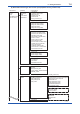
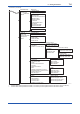
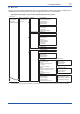
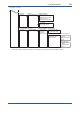
(2) Menu Tree
The menu tree of the device conguration tool of our recommendation is shown below. Refer to Subsection 8.2
“Calibration Instruments Selection” for the device conguration tool of our recommendation.
(a) Integral antenna type: single sensor input (Amplier housing code 7)
• UAPMO
• TRANSDUCER
• AI1 Temp
(Device Configuration)
• Device
Configuration
• Diagnostic
• Process Variable
Online Menu
• Configure/Setup
(UAPMO)
F0703-1.ai
• UAP Option
• Hardware Write Protect
• Static Revision
• Reset Energy Left
• Radio Silence
(Configuration)
• Version Revision
• CTS Version
• ITS Version
• Identification Number
(Identification)
• Configure/Setup
(TRANSDUCER)
• Tag Description
(Block Info)
• Model
• Serial Number
• Burn Out
• Wireless Status
• Display Selection
• LCD Mode
• YTA Option
(Configuration/Calibration)
• Configure/Setup
(AI1 Temp)
• Tag Description
(Block Info)
• Mode.Target
• Mode.Actual
• Mode.Permitted
• Mode.Normal
(Block Mode)
• Block Mode
• Concentrator OID
• Scale *
• Process Value Filter Time
• Lin Type*
• Sensor Connection *
• Bias *
• Selection of Reference Junction *
• External Reference Junction
Value *
• Process Value Type *
(Configuration)
• Sensor Serial Number
• Sensor Range *
• Cal Point Lo/Hi *
• Cal Point Clear*
• Reference Junction Unit *
(Others)
• Mode.Target
• Mode.Actual
• Mode.Permitted
• Mode.Normal
(Block Mode)
• Scale.EU at 100% *
• Scale.EU at 0% *
• Scale.Units Index *
• Scale.Decimal *
(Scale)
• Sensor Range.EU at 100%
• Sensor Range.EU at 0%
• Sensor Range.Units Index *
• Sensor Range.Decimal *
(Sensor Range)
• Special Cmd
(Other)
*: When the data of these parameters is rewritten, it is necessary to set the operational mode of the block to O/S (Out of Service).