
Instruction Manual

<5. Wiring>
5-1
IM 01C50E01-01EN
5. Wiring
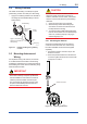
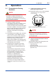
5.1 Notes on Wiring
IMPORTANT
• Apply a waterproong sealant to the threads
of the connection port. (It is recommended
that you use non-hardening sealant made of
silicon resin for waterproong.)
• Lay wiring as far away as possible from
electrical noise sources such as large
transformers, motors and power supplies.
• Remove the wiring connection dust-caps
before wiring.
• To prevent electrical noise, the signal cable
and the power cable must not be housed in
the same conduit.
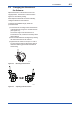
5.2 Cable Selection
A dedicated cable is used for connection between
the temperature sensor and the temperature
transmitter.
When a thermocouple is used as the temperature
sensor, a compensation wire that is appropriate for
the type of thermocouple (refer to compensating
cables for IEC584-3 thermocouples) must be used.
When a resistance temperature sensor (RTD) is
used as the temperature sensor, 2-core/3-core/4-
core cable must be used (refer to resistance
thermometer sensor IEC751). In a place where the
cable will be susceptible to the effect of noise, a
shielded cable must be used.
The terminal of the dedicated cable is a 4 mm
screw.
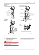
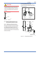
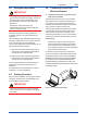
5.3 Cable and Terminal
Connections
F0501.ai
Figure 5.1 Input Terminal Connections
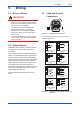
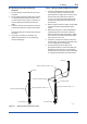
The temperature sensor is to be connected as
shown in Figures 5.2.
(B1)
(A1)
1
2
3
4
5
(–)
(+)
1
2
3
4
5
(B1)
(B1)
1
2
3
4
5
(–)
(+)
1
2
3
4
5
(+)
(A1)
(B2)
(B2)
(A2)
(A)
(B)
(B)
(B2)
(A2)
1
2
3
4
5
1
2
3
4
5
1
2
3
4
5
1
2
3
4
5
(–)
(+)
(B)
(A)
(B)
(B)
(B)
(A)
(A)
(A)
(B)
Thermocouple and
DC voltage
RTD and resistance
(3-wire)
Thermocouple +
RTD and resistance
(3-wire)
RTD and resistance
(2-wire)
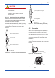
2 input (Amplifier housing code 8 and 9)
Thermocouple and
DC voltage
RTD and resistance
(2-wire)
RTD and resistance
(3-wire)
RTD and resistance
(4-wire)
1 input
F0502.ai
Figure 5.2 YTA510 Input Terminal Wire Connection
Diagram