User’s Manual YTA510 Temperature Transmitter IM 01C50E01-01EN IM 01C50E01-01EN Yokogawa Electric Corporation 7th Edition
i YTA510 Temperature Transmitter IM 01C50E01-01EN 7th Edition Contents 1. 2. Introduction................................................................................................ 1-1 1.1 Safe Use of This Product ................................................................................. 1-2 1.2 Radio Wave......................................................................................................... 1-2 1.3 Warranty..............................................................
ii 5.4 Wiring Cautions................................................................................................. 5-2 5.5 Mounting Antenna and Wiring.......................................................................... 5-2 5.6 6. 7. 5.5.1 Mounting the Antenna......................................................................... 5-2 5.5.2 Mounting External Antenna and Wiring Antenna Extension Cable.... 5-3 5.5.2.1 Mounting of External Antenna.........................................
iii 8. Maintenance............................................................................................... 8-1 8.1 General................................................................................................................ 8-1 8.2 Calibration Instruments Selection................................................................... 8-1 8.3 Calibration Procedure....................................................................................... 8-1 8.4 Disassembly and Assembly....
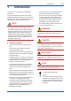
1. 1-1 <1. Introduction> Introduction Thank you for purchasing the YTA temperature transmitter. • Yokogawa assumes no responsibilities for this product except as stated in the warranty. Your YTA temperature transmitter was precisely calibrated at the factory before shipment. To ensure both safety and efficiency, please read this manual carefully before you operate the instrument.
1.1 Safe Use of This Product For the safety of the operator and to protect the instrument and the system, please be sure to follow this manual’s safety instructions when handling this instrument. If these instructions are not heeded, the protection provided by this instrument may be impaired. In this case, Yokogawa cannot guarantee that the instrument can be safely operated.
1.3 Warranty • The warranty shall cover the period noted on the quotation presented to the purchaser at the time of purchase. Problems occurring during the warranty period shall basically be repaired free of charge. <1. Introduction> 1-3 Trademarks In this document, trademarks or registered trademarks are not marked with “™” or “®”. Product names and company names in this document are trademarks or registered trademarks of the respective companies.
1.4 <1. Introduction> 1-4 ATEX Documentation This is only applicable to the countries in European Union.
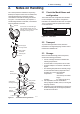
2-1 <2. Notes on Handling> 2. Notes on Handling The YTA temperature transmitter is fully factorytested upon shipment. When the YTA is delivered, check the appearance for damage, and also check that the transmitter mounting parts shown in Figure 2.1 are included with your shipment. If “No Mounting Bracket” is indicated, no transmitter mounting bracket is included.
NOTE When storing the instrument with a battery pack, it is recommended to put the instrument in Deep Sleep mode to conserve the batteries. For details on how to switch to Deep Sleep mode, refer to subsection 7.3.14 “Switching to the Deep Sleep Mode”. 2.4 Choosing the Installation Location Although the temperature transmitter is designed to operate in a vigorous environment, to maintain stability and accuracy, the following is recommended. 2-2 <2.
2.6 Insulation Resistance Test and Withstand Voltage Test (1) Overvoltage of the test voltage that is so small that it does not cause an dielectric breakdown may in fact deteriorate insulation and lower the safety performance; to prevent this it is recommended that the amount of testing be kept to a minimum. (2) The voltage for the insulation resistance test must be 500 VDC or lower, and the voltage for the withstand voltage test must be 500 VAC (50Hz ~ 60Hz) or lower.
WARNING The battery pack may be replaced in a hazardous area. The battery pack has surface resistivity greater than 1G ohm and must be properly installed in the enclosure of the transmitter. Care must be taken during transportation to and from the point of installation to prevent electrostatic charge build-up. 2.7.1 FM Approval Caution for FM intrinsically safe type. (Following contents refer “DOC. No. IFM038-A20”) Note 1.
<2. Notes on Handling> [Installation Diagram] Amplifier housing code 7 Hazardous Location Temperature Transmitter Battery pack 1 2 • • 3 4 5 Temperature Sensor (*1) • Amplifier housing code other than 7 • • • Hazardous Location Arrester (*1, *2) Antenna (*1) Antenna Connector 1 Temperature Transmitter Battery pack 2 3 4 5 Temperature Sensor (*1) (One or Two sensors) *1: These apparatus are simple apparatus. *2: Arrester may not be connected. F0204.ai Note 4.
<2. Notes on Handling> Note 2. Output Parameters • Sensor input circuit (Terminals 1 to 5 ) Uo: 6.6 V Io: 66 mA Po: 109 mW Co: 22 μF Lo: 8.1 mH • The above parameters apply when one of the two conditions below is given: - the total Li of the external circuit (excluding the cable) is < 1% of the Lo value or - the total Ci of the external circuit (excluding the cable) is < 1% of the Co value.
(2) Operation [Control Drawing] Amplifier housing code 7 Hazardous area Temperature Transmitter Battery pack WARNING 1 Take care not to generate mechanical sparking when access to the instrument and peripheral devices in a hazardous location.
2.7.4 IECEx Certification Caution for IECEx Intrinsically safe type. Note 1. Model YTA Series temperature transmitters with optional code /SS27 for potentially explosive atmospheres: • No. IECEx KEM 10.0073X • Applicable Standard: IEC 60079-0: 2011, IEC 60079-11: 2011, IEC 60079-26: 2006 • Type of Protection and Marking code: Ex ia IIC T4 Ga • Ambient Temperature: –50°C to 70°C • Enclosure: IP66/IP67 Note 2. Output Parameters • Sensor input circuit (Terminals 1 to 5 ) Uo: 6.
WARNING • Potential electrostatic charging hazard secure distance of 100mm from antenna. • Take care not to generate mechanical sparking when access to the instrument and peripheral devices in a hazardous location. 2.8 EMC Conformity Standards EN61326-1 Class A, Table 2 (For use in industrial locations), EN61326-2-3 CAUTION This instrument is a Class A product, and it is designed for use in the industrial environment. Please use this instrument in the industrial environment only.
Co-located: This transmitter must not be co-located or operated in conjunction with any other antenna or transmitter. FCC WARNING: Changes or modifications not expressly approved by the party responsible for compliance could void the user’s authority to operate the equipment. NOTE This equipment has been tested and found to comply with the limits for a Class A digital device, pursuant to part 15 of he FCC Rules.
3. 3-1 <3. Component Names> Part Names and Functions Antenna (Note 4) Terminal cover Grounding terminal CPU assembly Built-in indicator display RF assembly Write protection switch Slide Lock screw switch Transmitter section Amp.
4. 4.1 • <4. Installation> Installation Precautions Before installing the transmitter, read the cautionary notes in section 2.4, “Selecting the Installation Location.” For additional information on the ambient conditions allowed at the installation location, refer to subsection 10 “General Specifications.” • 4-1 NOTE 4.2 • • Mounting The mounting bracket shown in Figure 4.1 is used for the transmitter and is installed on 50A (2-inch) pipe.
4-2 <4. Installation> Horizontal Pipe Mounting (When using a horizontal pipe mounting bracket) U-bolt nut Horizontal pipe mounting bracket Spring washer (When using a vertical pipe mounting bracket) Bracket fastening bolt Vertical pipe mounting bracket Spring washer Transmitter fastening bolt Transmitter fastening bolt U-bolt nut Spring washer U-bolt Vertical Pipe Mounting Bracket fastening bolt U-bolt Wall Mounting Note: Wall mounting bolts are user-supplied. F0401.ai Figure 4.1 4.
4.4 <4. Installation> 4-3 Changing the Direction of the Antenna Adjust the direction of the antenna to be in the upright position. The direction of antenna is like Figure 4.2 at the factory setting. When adjust the electrical connection vertically, change the direction of the antenna. To change the installation angle, follow the procedure below. 1) Loosen the two mounting screws at the bottom of the antenna by using a 2.5 mm Allen wrench (see Figure 4.2).
5. 5.1 Wiring Notes on Wiring 5.3 Cable and Terminal Connections IMPORTANT • • • • 5-1 <5. Wiring> Apply a waterproofing sealant to the threads of the connection port. (It is recommended that you use non-hardening sealant made of silicon resin for waterproofing.) Lay wiring as far away as possible from electrical noise sources such as large transformers, motors and power supplies. Remove the wiring connection dust-caps before wiring.
5.4 <5. Wiring> Wiring Cautions Use metal conduit wiring or a waterproof gland (metal wiring conduit JIS F 8801) for cable wiring. • Apply non-hardening sealant to the threads of the wiring tap and a flexible fitting for secure waterproofing. Flexible fitting Temperature sensor signal Apply a nonhardening sealant to the threads for waterproofing. Wiring conduit Tee 5.
5-3 <5. Wiring> CAUTION When installing the antenna, screw the antenna by tightening the lower nut part. Screwing the antenna by holding the antenna body may cause failure such as cable disconnection. The same manner should be taken when unscrewing the antenna. Fixing of External Antenna Fix an external antenna appropriately using the bracket provided as the external antenna option to 50 mm (2-inch) pipe. Antenna body Vertical pipe mounting Nut part Horizontal pipe mounting F0505.ai Figure 5.
5-4 <5. Wiring> 5.5.2.2 Wiring of Antenna Extension Cable Mounting Procedure of External Antenna 1. Fix the bracket by U-bolt and nut to 50 mm (2inch) pipe. 2. Fix the antenna extension cable to the bracket 1 using the provided nut with a torque of 6 to 7 N∙m as shown in the Figure 5.6. Use the nut which is attached to the antenna extension cable. 3. Screw the antenna into the antenna connector of the antenna extension cable on the bracket 1.
5-5 <5. Wiring> Antenna side CAUTION • Use the dedicated antenna extension cable provided by Yokogawa as accessories for the transmitters. • The antenna extension cable and temperature sensor cable should not be bundled together. Protect by self-bonding tape 5.5.2.3 Mounting of Arrester and Wiring Mount an arrester between the extension cables and connect the grounding cable to the grounding terminal of the arrester as required.
<5. Wiring> 5-6 CAUTION Grounding is required for safe operation. The temperature sensor cable sheild should be connected to grounding terminal inside of the housing.
6-1 <6. Operation> 6. Operation 6.1 Preparation for Starting Operation ■ Confirm that transmitter is operating properly by integral indicator. If the transmitter is faulty, an error code is displayed. NOTE Self-diagnostic error on the integral indicator (Faulty transmitter) It is required to set security and network information to enable the transmitter to be connected to the Field Wireless Network. For more details, refer to subsection 6.4 “Connecting to the Field Wireless Network”.
6.2 Zero-gain Adjustment IMPORTANT After performing zero-gain adjustment, do not power off the transmitter immediately. Turning off the power within 30 seconds resets the zerogain adjustment value to the value before the adjustment. Furthermore, setting the sensor type automatically resets the zero-gain adjustment value to the factory setting When the preparation for starting operation is completed, perform a zero-gain adjustment as necessary.
■ Provisioning work This subsection describes provisioning work using FieldMate as the provisioning device. Provisioning work performs provisioning for each field wireless device using FieldMate and an infrared adapter. When using the Yokogawa recommended near infrared adapter for the provisioning device, the distance between the front glass of this instrument and the infrared surface of the near infrared adapter should be within 30 cm.
<6. Operation> (a) Deep sleep 6-4 NOTE If the transmitter searches the Field wireless Network for long time ambient temperature condition, sometimes error "AL.20 LOWBAT" is displayed on the Integral Indicator. Even though using new batteries, it can occur. It occurs because of battery characteristics. After joining to the Field Wireless Network, this error will be cleared within one hour if battery has no failure. F0604.ai (b) Ready and pause 6.
7. Setting Parameters This transmitter can remotely handle sensor type changes, range changes, Tag No. setup, monitoring of self-diagnostic results, according to communication with the field wireless configuration tool or the device configuration tool. 7.1 7-1 <7. Setting Parameters> Environment for parameter setting After installing the battery pack, perform provisioning and have the instrument join the field wireless network.
7.3 Setting Parameters 7.3.1 Parameter Usage and Selection Before setting a parameter, please see the following table for a summary of how and when each parameter is used. The integral antenna type is applicable only for a single sensor input which is assigned to AI1. The detachable antenna type is applicable for dual sensor input assigned to AI1/AI2 accordingly. Table 7.1 7-2 <7.
7-3 <7. Setting Parameters> 7.3.2 Function Block and Menu Tree (1) Function Block The function of this transmitter is shown below. A specific function might not be able to be used according to the field wireless configuration tool used. When the field wireless configuration tool of our recommendation is used, the software attached to the Field Wireless Integrated Gateway is necessary for setting the dotted line part. Refer to Subsection 8.
<7. Setting Parameters> Online Menu (Continued) (TRANSDUCER) • Block Info • Configuration /Calibration • Others 7-4 (Block Info) • Tag Description (Configuration/Calibration) • Model • Serial Number • Burn Out • Wireless Status • Display Selection • LCD Mode • YTA Option (Other) • Special Cmd (AI1 Temp) (Block Info) • Block Info • Block Mode • Dynamic Variables • Configuration • Others •Tag Description (Block Mode) • Mode.Target • Mode.Actual • Mode.Permitted • Mode.
7-5 <7. Setting Parameters> (b) Detachable antenna type: dual sensor input (Amplifier housing code 8 and 9) Online Menu • UAPMO • UDO • CO • TRANSDUCER • AI1/AI2 Temp (UAPMO) • Configuration • Diagnostics • Alerts • Power Status • Identification (Configuration) • UAP Option • Hardware Write Protect • Static Revision • Reset Energy Left • Radio Silence • Energy Harvest Type (Diagnostics) • Diagnostic Status • Diagnostic Status Detail.1 • Diagnostic Status Detail.
7-6 <7.
7-7 <7. Setting Parameters> (2) Menu Tree The menu tree of the device configuration tool of our recommendation is shown below. Refer to Subsection 8.2 “Calibration Instruments Selection” for the device configuration tool of our recommendation.
7-8 <7. Setting Parameters> Online Menu (Continued) (Diagnostic) • UAPMO (UAPMO) • Device Diagnostics (Diagnostics/Alerts) • Diagnostic Status • Diagnostic Status Detail1, Diagnostic Status Detail2 • Diagnostic Switch • Diagnostic Configuration (Power Status) • Energy Left • Power Supply Status (Process Variable) (AI1 Temp) • AI1 Temp • Process Variable (Dynamic Variables) (Process Value) • Process Value • Simulation • Reference Junction Temp • Process Value.Status • Process Value.
<7.
7-10 <7. Setting Parameters> Online Menu (Continued) (AI1/AI2 Temp) • Configure/Setup (Block Info) • Tag Description (Block Mode) • Mode.Target • Mode.Actual • Mode.Permitted • Mode.Normal (Configuration) (Block Mode) • Block Mode • Mode.Target • Concentrator OID • Mode.Actual • Scale * • Mode.Permitted • Process Value Filter Time • Mode.Normal • Lin Type* • Sensor Connection * (Scale) • Bias * • Selection of Reference Junction * • Scale.EU at 100% * • External Reference Junction Value * • Scale.
7.3.3 Parameters for Wireless Communication (1) Network Information Concentrator object block: Configuration. The network-related information can be checked. (2) Update Time CO block: Data publication period Sets the update time value to 1 to 3,600 seconds. When using two temperature sensors for dual input type, the minimum update time is 2 seconds. The setting affects the battery life.
7-12 <7. Setting Parameters> 7.3.4 Tag and Device Information 7.3.6 Power Saving Mode Setting If these are specified when ordering, the designated Tag No. and device information are set and shipped. This function is applicable for dual input type with a detachable antenna, Amplifier housing code 8 and 9.
7-13 <7. Setting Parameters> ■ Procedure to call up the upper limit setting parameter (EU at 100%) AI1/AI2 block: Scale : EU at 100% Set the lower limit setting parameter (EU at 0%) and upper limit setting parameter (EU at 100%) to the unit specified in the unit parameter (Units Index). 7.3.9 Input Sensor When changing the sensor type, it is necessary to change the parameters related to the sensor type. The setting items are the sensor type and the number of cables.
1) Setting the Sensor Type ■ Procedure to call up the sensor type setting parameter (Lin Type) ■ Procedure to call up external temperature Compensation parameter(External Reference Junction Value) AI1/AI2 block: External Reference Junction Value AI1/AI2 block: Lin Type Set the sensor type. In the CJC function parameter (Selection of Reference Junction), the cold junction temperature value of the thermocouple is selected the external (2), set the external compensation temperature.
- Setting to enable or disable the hardware write protection switch. - Setting to enable or disable changing the setting to the Diagnostic Switch and Diagnostic Configuration parameters. 2) Procedure to call up the protection setting display parameter (Hardware Write Protect) UAPMO block : Hardware Write Protect The Hardware Write Protect parameter enables the switch status of hardware write protection to be displayed.
ZERO GAIN Output Input Figure 7.3 F0705.ai Trim function images IMPORTANT Setting the sensor type automatically resets the zero-gain adjustment value to the factory setting. 2) Clearing the Adjustment Value The adjustment value set with input adjustment can be cleared and reset to the factory setting. ■ Procedure to call up the adjustment value reset parameter (Cal Point Clear) AI1/AI2 block: Cal Point Clear Set the Cal Point Clear parameter to Clear. 7.3.14 7-16 <7.
7.4 Self-Diagnostics ■ Procedure to call up the self-diagnostic parameter 7.4.1 Identify Problems by Using the Communicator UAPMO block: Diagnostic Status The configuration tool allows checking the self-diagnosis results and setting errors of this instrument. First, check Diagnostic Status of the self-diagnostic result. Table 7.
Checking the Diagnostic Status category allows taking the proper action. The Diagnostic Status contents are common for all ISA devices, and the setting for the Diagnostic Status category can be changed. For further details, refer to Diagnostic Status Detail. In Diagnostic Status Contents that can be diagnosed by the YTA, the alert category set in Out of Service can be changed to Check function. To do so, follow one of the two procedures below. a) UAPMO block: UAP Option select “enable”.
Table 7.
8. 8.1 8-1 <8. Maintenance> Maintenance General 8.2 Maintenance of the transmitter is easy due to its modular construction. This chapter describes the procedures for calibration, adjustment, and the disassembly and reassembly procedures required for component replacement. Transmitters are precision instruments. Please carefully and thoroughly read the following sections for information on how to properly handle them while performing maintenance.
Example of wiring for thermocouple or DC voltage input YTA sensor input terminal 1 2 3 4 5 YTA sensor input terminal 1 2 3 4 5 8.4 Disassembly and Assembly CAUTION (+) (−) DC voltage generator Example of wiring for RTD 4-wire type (A) (A) (B) (B) Variable resistor F0801.ai Figure 8.1 8-2 <8.
Table 8.2 8-3 <8. Maintenance> Tools for Disassembly and Reassembly Tool Phillips screwdriver Slotted screwdriver Allen wrenches Wrench Torque wrench Adjustable wrench Socket wrench Socket driver Tweezers Quantity Remarks 1 JIS B4633, No. 2 Press forward 1 3 1 1 1 1 1 1 Output terminal cable JIS B4648 One each, nominal 3, 4 and 2.5 mm Allen wrenches Width across flats, 17 mm Stud Integral Indicator Boss CPU assembly RF assembly Mounting screw Width across flats, 16 mm Width across flats, 5.
8-4 <8. Maintenance> 8.4.3 Replacing the CPU Assembly 8.4.4 Replacing the Battery Pack This subsection describes how to replace the CPU assembly (see Figure 8.2). Regarding the transmitter with intrinsically safe approval, the battery pack can be replaced without removing the device in hazardous area. ■ Removing the CPU assembly 1) Remove the cover. Remove the Integral indicator and the RF assembly (refer to subsections 8.4.1 and 8.4.2). 2) Disconnect the power cable.
8-5 <8. Maintenance> 8.4.5 Replacing the Batteries 8.4.6 Handling Batteries The batteries in the battery pack can be replaced. Batteries are not installed when shipped from the factory. Assemble the battery pack as follows. This battery pack uses two primary lithium/ thionyl chloride batteries. Each battery contains approximately 5 grams of lithium, for a total of 10 grams in each pack.
Transportation of products containing lithium batteries Batteries used for this transmitter contain lithium. Primary lithium batteries are regulated in transportation by the U.S. Department of Transportation, and are also covered by the International Air Transport Association (IATA), the International Civil Aviation Organization (ICAO), and the European Ground Transportation of Dangerous Goods (ARD). It is the responsibility of the shipper to ensure compliance with these or any other local requirements.
<8. Maintenance> 8-7 8.5.2 Example of Troubleshooting Flow The following shows an example of the flow for troubleshooting. Refer to this example and Table 8.3 “Problems, Causes and Countermeasures” and locate the problem and take the corresponding countermeasure. The following phenomena indicate that this instrument may be out of operation. [Example] • No output signal is delivered. • Process variable changes but the output signal remains unchanged.
8-8 <8. Maintenance> Table 8.3 Cause and Countermeasure Observed Problems Output fluctuates greatly. Possible Cause Countermeasure Related Parameter Input adjustment by user was Set or clear the user adjustment • Lin Type not correctly done. value. • Sensor Range Damping adjustment is not Set the damping adjustment to correct. 0. • P rocess Value Filter Time Transmitter outputs fixed Input adjustment by user was Set or clear the user adjustment • Lin Type current. not correctly done. value.
Integral indicator AL.20 LOWBAT *3 Factory NAMUR category M Bit Diagnostic Status Bit 19 Power is low: maintenance need mid-term LOWBAT Bit 20 Power is critical low: maintenance need short term CRITICAL LOWBAT Bit 20 Power is critical low: maintenance need short term Bit 21 Fault prediction: Maintenance required *4 *5 AL.23 FIRM.C M Diagnostic Status Detail LOWBAT FOR DEEPSLEEP FIRMWARE CONDITION CHECK SENSOR1 TEMP HI AL.40 S1.
Integral indicator Factory NAMUR category Bit Diagnostic Status Diagnostic Status Detail SENSOR1 SPAN ADJ ERR AL.50 S1.SPAN SENSOR1 ZERO ADJ ERR AL.51 S1.ZERO Bit 25 Faults in sensor or actuator element *4 SENSOR2 SPAN ADJ ERR AL.53 S2.ZERO SENSOR2 ZERO ADJ ERR AL.52 S2.SPAN *4 AL.60 AI1.OS AI1 O/S MODE C Bit 24 Out of service AL.61 AI2.OS*4 Bit 17 *1: AI2 O/S MODE AI1 SIMULATE MODE AL.64 AI1.SIM AL.65 AI2.SIM*4 8-10 <8.
9. Parameter Summary Table 9.1 Parameter Summary Object ID 1. UAPMO block 9-1 <9. Parameter Summary> Attribute Label ID 1 Version Revision 10 Static Revision 64 Identification Number CTS Version 65 66 67 68 69 70 102 103 104 105 Description Default value Handling Indicates the application revision of YTA. This revision changes --when the application software is downloaded. Indicates the revision level of the fixed parameters of UAP.
Object ID 1. UAPMO (continued) 9-2 <9. Parameter Summary> Attribute Label ID 106 EH Type *2 107 Power Supply Voltage *2 110 Hardware Write Protect 111 Radio Silence Description Available to write note into this parameter. Indicates the measured power supply voltage (V). Default value Handling ----- Allows recognizing the status of the hardware write protection --switch.
Object ID 1. UAPMO (continued) 2. UDO block Attribute ID Label Description Default value Handling 123 Faults process influence Alert*2 The On/Off or priority for Faults process influence Alert can be set. 1. On/Off setting 0 = FALSE, 255 =TRUE 2. Alert report priority: 0 to 15 Not available for YTA. 1. TRUE 2. 15 W 124 Faults noncompliance Alert*2 The On/Off or priority for Faults non-compliance Alert can be set. 1. On/Off setting 0 = FALSE, 255 =TRUE 2.
Object ID Attribute ID 4. 1 TRANSDUCER 2 block 3 4 5 6 7 8 9 11 12 14 5. AI1 block 6. AI2 block*2 9-4 <9. Parameter Summary> Label Tag Description Model Serial Number Burn Out*3 Hardware Burn Out Switch*2 Wireless Status Memo field available to write anything. Indicates the model name of the transmitter. Indicates the device number of the transmitter. Indicates the direction of the burnout switch on the integral indicator.
Object ID 5. AI1 block 6. AI2 block*2 (continued) 9-5 <9. Parameter Summary> Attribute Label ID 4 Scale 26 27 28 29 30 51 52 53 57 58 59 61 102 Tag Description Description Allows specifying the upper or lower limit for the PV scaling, unit code, etc. 1.EU at 100%: Indicates the upper limit to the PV value. 2.EU at 0%: Indicates the lower limit to the PV value. 3.Units Index: Indicates the set unit used for the PV value. 4.
Object ID 5. AI1 block 6. AI2 block*2 (continued) 9-6 <9. Parameter Summary> Attribute Label ID 103 Cal Point Lo 104 Cal Point Hi 105 Cal Point Clear 106 Process Value Type 107 Reference Junction Unit 108 Burn Out Type*2 Description Sets the zero-point adjustment for the input adjustment (zerogain adjustment ) of the sensor. Be sure to perform adjustment with Cal Point Lo (zero-point) first. Sets the gain-point adjustment for the input adjustment (zerogain adjustment) of the sensor.
Table 9.2 Diagnostic Status Detail Bit Diagnostic Status Detail Bit22 Bit21 SENSOR1 ZERO ADJ ERR SENSOR2 SPAN ADJ ERR *1 Bit20 Bit15 Bit14 Bit13 Bit12 SENSOR2 ZERO ADJ ERR *1 AI1 O/S MODE AI2 O/S MODE *1 AI1 SIMULATE MODE AI2 SIMULATE MODE *1 Diagnostic status NAMUR assignment bit Description Diagnostic Status Detail.
10-1 <10. General Specifications> 10. General Specifications 10.1 General Specification Communication Protocol ISA100.11a protocol Data Rate 250 kbps Frequency 2400 - 2483.5 MHz license free ISM band Radio Security AES 128 bit codified RF Transmitter Power Max. 11.6 dBm (fixed) Antenna +2 dBi Omni directional monopole type Measurement Range See Table 10.1 Accuracy See Table 10.1 Cold Junction Compensation Accuracy ± 0.5°C Ambient Temperature Effect See Table 10.
<10. General Specifications> 10-2 R&TTE Conformity Standards ETSI EN 300 328, ETSI EN 301 489-1, ETSI EN 301 489-17, EN61010-1, EN61010-2-030, EN62311 • Indoor/Outdoor use Safety Requirement Standards EN61010-1, EN61010-2-030 • Altitude of installation site: Max.
Table 10.1 10-3 <10.
<10. General Specifications> 10-4 10.2 Model and Suffix Codes Model Suffix Codes Descriptions YTA510 . . . . . . . . . . . . . . . . . . . . . . Temperature Transmitter Output Signal -L. . . . . . . . . . . . . . . . . . . . . Wireless communication (ISA100.11a) Amplifier Housing 7 . . . . . . . . . . . . . . . . . . . Single input type, cast aluminum alloy with integral antenna 8 . . . . . . . . . . . . . . . . . . . Dual input type, cast aluminum alloy with detachable antenna (2 dBi)*3 9 . . . . .
10-5 <10. General Specifications> 10.
<10. General Specifications> 10-6 10.5 Dimensions 2-inch horizontal pipe mounting (Amplifier housing code 7) Unit: mm (approx. inch) 191 (7.52) 88 (3.46) 82*2 (3.23) 39 (1.54) Mounting bracket Ø110 (4.33) Ground terminal Electrical connection 56 (2.20) 2-inch pipe (O. D. 60mm) 40 (1.57) 15 (0.59) 35 (1.38) Ø110 (4.33) Electrical connection 188 (7.40) Terminal cover 128 (5.04) Integral indicator B 103 (4.06) 248*1 (9.76) A 24 (0.94) 70 (2.76) 90 (3.54) 140 (5.
<10. General Specifications> 10-7 Terminal Configuration Infrared Configuration Ground terminal Infrared port F1003.ai F1004.
i Revision Information Title : YTA510 Temperature Transmitter Manual No. : IM 01C50E01-01EN Edition 1st 2nd Date Aug. 2010 Oct. 2010 3rd Apr. 2011 Page — 2-5 2-7 10 - 4 ― 4th 5th 6th 7th Dec. 2011 Aug. 2012 June 2013 Jan. 2014 8-5 ― ― ― Revised Item New publication 2.7.3 Add CENELEC ATEX (KEMA) Certification 2.7.4 Add IECEx Certification 10.4 Add option code /KC27 and /SS27. • Adapted to device configuration tool with infrared communication function.