
Manual


13-15
IM 04L21B01-01EN
Specifications
3
2
1
4
5
6
7
8
9
10
11
12
13
14
App
Index
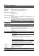
Power Monitor (/PWR1)
Unless otherwise specified, the performance values listed here were recorded under the following standard operating conditions:
23 ± 2°C, 55 ± 10%RH; power supply frequency: 50/60 Hz ± 1% or less; rated input: ±1% or less, power factor: 1 ± 1% or less;
warm-up time: 30 minutes or more; and a location in which oscillations and other factors do not affect the operation of the
instrument.
Item Specifications
Measurement element By including power measurement elements in an expression, you can measure a variety of power
values.
Active power, regenerative electric power, reactive power, apparent power, voltage, current,
frequency, power factor (LEAD: –, LAG: +), and
electric energy (active energy, regenerative energy, reactive energy—LAG: +, reactive energy—
LEAD: —, and apparent energy)
* The LEAD/LAG sign is calculated from the phase difference between P1 (voltage) and I1
(current).
Phase and wiring system Single-phase two-wire system, single-phase three-wire system, and three-phase three-wire system
Frequency 45 to 65 Hz
Rated input voltage
Rated Voltage Voltage Range (Variable) Allowable Input Voltage Crest
Factor
120 V 120 V 150 V 2
240 V 240 V 300 V 2
Rated input current
Rated Current Current Range (Fixed) Allowable Input Current Crest
Factor
1 A 1 A 1.2 A 2
Allowable input range 150 Vrms (when the voltage range is set to 120 V), 300 Vrms (when the voltage range is set to 240 V),
and 1.2 A (when using current input)
Rated input power and measuring range
Single-phase two-wire system
Input (AC) Input Measuring Range
1
Approximate Consumed VA
Rated Power Voltage Current
120 V/1 A 100 W –120 to 120 W 0.2 VA
0.2 VA
240 V/1 A 200 W –240 to 240 W 0.4 VA
Single-phase three-wire system
Input (AC) Input Measuring Range
Approximate Consumed VA
Rated Power Voltage Current
200 V/1 A 200 W –240 to 240 W 0.2 VA/phase 0.2 VA/phase
Three-phase three-wire system
Input (AC) Input Measuring Range
Approximate Consumed VA
Rated Power Voltage Current
120 V/1 A 200 W –240 to 240 W 0.2 VA/phase
0.2 VA/phase
240 V/1 A 400 W –480 to 480 W 0.4 VA/phase
The input measuring range when you are using a VT and CT is calculated using the following
equation. The measuring range must be within the input measuring ranges listed above, and the
primary side input power
2
must be less than 10 GW.
1 Input measuring range (W) = Primary side input power
2
in W/(VT ratio × CT ratio).
2 Primary side input power = Secondary side rated power in W × 1.2 × VT ratio × CT ratio.
Measuring range Power factor: (LEAD) 0.5 to 1 to (LAG) 0.5
Frequency: 45 to 65 Hz
13.5 Options