
Manual


12-13
IM 04L21B01-01EN
Installation and Wiring
3
2
1
4
5
6
7
8
9
10
11
12
13
14
App
Index
Checking the Connection Status on the FX Display
• Checking the Connection Status in the Status Indication Section of the FX Display
You can use the Ethernet Link indicator that is located on the right side of the status
indication display section of the basic setting mode display to check the connection
status of the Ethernet interface. To display the basic setting mode display, press
MENU to display the setting menu, and then hold down FUNC for 3 seconds or more.
• Checking the Connection Status in the Upper Right Corner of the Communication Log
Display of the FX
You can use the Link indicator that is located in the upper right of the communication
log display to check the connection status of the Ethernet interface.
Indicator Connection Status of the Ethernet Interface
Illuminated (green) The Ethernet interface is electrically connected.
Off The Ethernet interface is not electrically connected.
Connecting to the Power Measurement Terminal (/PWR1)
WARNING
• To prevent electric shock while wiring, make sure that the power supply is turned
off.
CAUTION
• If you are not using a VT and a CT, do not ground the input circuit.
• If you are wiring through conduits (metal tubes designed for wiring), install the
CT (current transformer) inside a panel.
• Wire the voltage input and the current input within the same circuit.
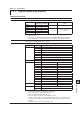
Single-phase two-wire system
P1P21S1L
Power supply
1 2
K
L
CT
Load
Fuse
k
l
VT
U
V
1L
1S
P1
P2
u
v
12.5 Optional Terminal Wiring