
Manual


12-10
IM 04L21B01-01EN
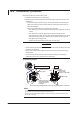
The following figures show the terminal positions for each option when only that option is
installed. Even if you have installed a number of options, the individual terminal positions
of the options do not change (except for the case where you have installed both the
/TPS2 and /A1 options; in this case, the /A1 terminal positions are different).
1 to 8: Remote control terminal
number
C: Common
NC: Normally closed
C: Common
NO: Normally opened
NC
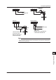
Remote control input
Alarm output, FAIL, Status
H and L
Pulse input
+ and –
Transmitter power supply
output
Symbols such as “NC” indicate the terminal functions.
A terminal that is not used.
Alarm outputAlarm output
Alarm outputAlarm output
Alarm output
Alarm output
Alarm output
Memory
end
Remote control input
Remote control input
Pulse input
Voltage inputCurrent
input
Current
input
Transmitter power supply output
Transmitter power supply output
NC
C
NO
/A1 /A2
01
NC
C
NO
02
NC
C
NO
01
NC
C
NO
NC
C
NO
0102
NC
C
NO
NC
C
NO
NC
C
NO
02
NC
C
NO
03
NC
C
NO
04
NC
C
NO
/A3 /A4A
01
NC
C
NO
NC
C
NO
NC
C
NO
02
0506
C
NO
C
NO
C
NO
C
NO
C
NO
C
NO
C
NO
C
NO
C
NO
C
NO
C
NO
C
NO
RS-422A/485
NC
C
NO
03
NC
C
NO
04 010203040506
07
0809101112
FAIL
/C3
/F1
FG SG
SDB SDA RDB RDA
/PM1
/R1
L H L H L H 4 23 1 C5 8 7 6 4 23 1 C5
/PWR1
3S 1L 1S P1P2P33L
/TPS2
/TPS4
+- +- +- +-+- +-
/A1 when installed in the FX with a /TPS2
12.5 Optional Terminal Wiring