
Manual


12-6
IM 04L21B01-01EN
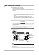
Arrangement of the Input Terminals
Input terminal block
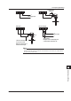
Input terminal block
of the FX1002
Input terminal block
of the FX1004
Input terminal block
of the FX1006
Input terminal block
of the FX1008
Input terminal block
of the FX1010
Input terminal block
of the FX1012
For TC input, use shielded compensating lead wires for wiring.
For RTD input, lead wire resistance per wire of 10 Ω or less. Make the resistances of
the three wires equal.
For DCA input, example: for 4 to 20 mA input, use a shunt resistor of 250 Ω ± 0.1%.
+/A
/b
CH1
–/B
CH2
+/A
/b
CH1
–/B
CH2CH3CH4
+/A
/b
CH1
–/B
CH2CH3CH4CH5CH6
+/A
/b
CH1
CH7
–/B
CH2
CH8
CH3CH4CH5CH6
+/A
/b
CH1
CH7
–/B
CH2
CH8
CH9CH10
CH3CH4CH5CH6
+/A
/b
CH1
CH7
–/B
CH2
CH8
CH9CH10CH11CH12
CH3CH4CH5CH6
12.4 Input Signal Wiring