MW100 CAN Bus Module Configuration Tool (MX118-CAN-M30/S1) User’s Manual 1 All Rights Reserved.
Contents 1. Before Using the Software ....................................................................................................................... 3 1.1. Explanation of Functions .................................................................................................................. 3 1.2. MX118 Part Names and Functions ................................................................................................... 3 1.2.1. Operation Guide ............................................
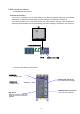
1. Before Using the Software 1.1. Explanation of Functions Overview of Functions A one-to-one connection can be made between the MX118-CAN-M30 CAN Bus Input Module (hereinafter, the MX118) and a PC allowing specific settings to be entered on the MX118. The sofware enables you to enter MX118 CAN bus communication settings, enter conditions for extracting measured data, save and load settings, print lists of settings, and perform other functions. PC Serial port for settings MX118 MW100 main module 1.2.
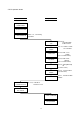
1.2.1. Operation Guide Op. on Main Unit Op. on PC Set up MW100, Install MX118 Connect power cable Connect serial cable Section 2.1, Connecting the MX118 Start configuration tool Enter serial comm. settings Set slot width Set bit rate Set msg. format/ID Enter channel settings Send settings Place MX118 in Measurement mode Sec., 2.12, Switching to Measurement mode Connect to CAN bus network System configuration Set up MW100 4 Section.1.6, Launching/Exiting Setting Software Sec. 2.
1.3.PC System Requirements PC A PC with an Intel Pentium III, 800-MHz CPU or higher and at least 256 MB of memory. OS (Operating System) Windows 2000 SP4 or later, or Windows XP SP2 or later (recommended). CD-ROM Drive A CD-ROM drive compatible with the OS. The drive is used to install the software. Free Hard Disk Space 10 MB or more. Display XGA (1024 × 768 resolution) or higher and capable of displaying 65535 or more colors. Serial Port An RS-232 port available to the OS.
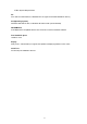
1.4. Setting Up the Software The following procedures apply to software installation on Windows XP. 1. Turn ON the power to the PC and start Windows. You must log into Windows with Administrator privileges in order to install the software. This is also the case when using Windows 2000. If Autorun Is Enabled 2. Insert the CD-ROM into the drive. The language selection screen in displayed. 3. Select the desired language. The setup program starts automatically. Proceed to step 4. If Autorun Is Disabled 2.
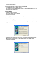
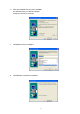
6. Enter the installation directory then click Next. The default directory is C:MX118 CAN Bus. Change the directory if necessary. 7. Click Next to start the installation. 8. Click Finish to complete the installation.
Installation Results If the software is properly installed, a folder named MX118 CAN Bus is created in the specified directory (on the C: drive by default). MW118 CAN Bus is registered in the program list, and MW118 CAN Bus Module Configuration Tool is registered in its sub list.
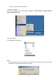
1.5. Launching and Exiting the Software Launching the Software As shown in the figure below, choose Start > Programs > MX118 CAN Bus > MX118 CAN Bus Module Configuration Tool. Exiting the Software Choose Exit from the File menu. Note When exiting the program, if the settings were changed from the last time they were saved, a dialog box appears confirming whether to save the changes.
2. Using the Configuration Tool 2.1. Connecting the MX118 Perform the following procedure to connect the MX118 to the PC and place it in Setting mode. 1. 2. Install the MX118 in the MW100. Connect the SERIAL connector of the MX118 to the PC’s RS232 port. The MX118 uses a 9-pin D-sub connector. Connect to the PC’s communication port as follows. PC COM port SD RD SG MX118 SERIAL 3:TXD 2:RXD 5:GND Wiring serial communications 1 2 6 7 3 4 5 8 9 Serial comm. connector pin no’s 3.
2.2. Serial Communication Settings Enter serial communication settings to configure the MX118. 1. Choose Communication > Settings. Or, click the Communication Settings icon on the toolbar. Click here or 2. 3. 4. Select the port to be used. Select a baud rate of 9600 bps or 57600 bps. Click the OK button to enter the settings. Port Baud Rate Explanation Port Enter the communication port of the PC connected to the MX118.
2.3. CAN Communication Settings (General Screen) Enter the slot width and CAN communication related settings. If the General screen is not displayed, click the General tab. 1. 2. 3. Select a slot width from 1-3 depending on the number of channels you wish to measure. Select a CAN bit rate for the CAN bus. If you wish to enter detailed settings related to bit timing, click the More button.
CAN Bit Rate (bps) You can set the speed of CAN bus communication. Select a bit rate from the following values. If you select Other, the detailed setting screen is displayed automatically. For the default bit timing in the various bit rates, see appendix 4.2, “Default Bit Timing Values.” 10 Kbps, 20 Kbps, 33.3Kbps, 50 Kbps, 62.5 Kbps, 83.
Baud Rate Prescaler (BRP) You can set the baud rate prescaler value. The available setting range is 1-256. Time Quanta Count (TQC) You can set the number of divisions of 1 bit. The available setting range is 8-25. TQC = SS + TSEG1 + TSEG2 Synchronization Segment (SS) The synchronization segment is fixed to 1. TSEG1(PRSEG + PHSEG1) You can set the total value for the propagation time segment and phase buffer segment 1 in the range from 4 to 16.
2.4. Setting the Message ID (Message Screen) You can enter settings related to the CAN message ID. If the Message screen is not displayed, click the Message tab. 1. 2. Select a message number format of OFF, Standard, or Extended. Enter the CAN message ID to be measured under BASE-ID (or BASE-ID and EXT-ID) using hexadecimal notation. Format BASE-ID EXT-ID Explanation Format You can set the format for the CAN message to be measured. Select OFF for the format of message numbers you will not use.
2.5. Channel Settings (Channel Screen) For each measurement channel, you can enter settings related to extracting and normalizing measured data from CAN messages. If the Channel screen is not displayed, click the Channel tab. 1. 2. 3. 4. Select the message numbers for which IDs of the data to be measured were set. Select Value Type, Start Bit Pos, Bit Length, or Endian depending on the data to be measured. The Start Bit Pos and Bit Length settings are fixed when Value Type is selected.
Start Bit Pos. You can specify a start bit position for extraction of data to be measured included in the data field. Enter the lsb number of the measured data. See below for how to count bit numbers in the MX118. The values that can be selected vary depending on the Value Type setting. Signed: 0–62 Unsigned: 0–63 Float: 0–32 Double: 0 (fixed) Bit Length Specify the data to be measured in terms of the number of bits.
Value Min. / Max. You can enter the upper and lower limits of measured data. The values that can be entered vary depending on the Value Type and Bit Length settings. Ensure that Value Min < Value Max. Value Type:Signed Bit Length Ex. of Available Setting Range 8 -128–127 16 -32768–32767 32 -2147483648–2147483647 64 -9223372036854775808–9223372036854775807 Value Type:Unsigned Bit Length Ex.
2.6. Copying and Pasting Settings Settings in the Message and Channel screens can be copied to other message numbers or channels. 1. Click to select the message or channel number to copy. The selected item changes color, and the Copy button is enabled. Drag to select a continuous range to copy. Click or drag source to select 2. copy Click the Copy button. The selection is copied, and the Paste button is enabled. Click the Copy button 3. Click the message or channel number(s) in which to paste.
2.7. Sending and Receiving Settings Receiving Settings You can receive settings from the MX118 and load them onto the software. 1. Choose Communication > Receive Settings. Or, click the Receive Settings icon on the toolbar. Click here or 2. The Receive Settings dialog box opens. Click OK to receive the settings. Settings currently being edited in the Configuration Tool are overwritten by the received settings. Sending Settings Settings entered on the Configuration Tool can be sent to the MX118. 1.
2.8. Displaying Module Information You can acquire information about the MX118 module connected to the PC. 1. 2. Choose Communication > Module Info. The module information is displayed. Model No. Firmware Version Slot No. Max Slot Width Update Explanation Model No. Displays the model name of the module. Firmware Version Displays the firmware version of the module. Slot No. Displays the slot number (0-5) of the installed module.
2.9. Saving and Loading Settings Saving Settings You can save settings created on the configuration tool to a file. 1. Choose File > Save or Save As. or 2. If you select Save As, or if you click Save to save settings for the first time, the Save As dialog box opens. Enter the filename in the Save As dialog box and click the Save button. If you enter an existing filename, a dialog box is displayed prompting you to confirm whether to overwrite the existing file.
Loading Settings Files You can load a previously saved settings file. 1. Choose File > Open. Or, click Open on the toolbar. Click here or 2. Select the file to load in the Open dialog box and click the Open button.
2.10. Creating New Settings You can initialize the settings. Choose File > New. Or, click New on the toolbar. Click here or Note When creating new settings, if the settings were changed from the last time they were saved, a dialog box appears confirming whether to save the changes.
2.11. Printing Settings You can print a list of settings, preview printing, and enter printer settings. Print 1. Choose File > Print. Or, click the Print icon on the toolbar. 2. The Print dialog box opens. In the Print dialog box, select the printer, print range, and the number of copies, and then click the OK button. Click here or To print the detailed settings of bit timing, display the detailed settings in the General setting screen.
Print Preview Choose File > Print Preview. An image of the printout is displayed. Print Setup... Choose File > Print Setup. The Print Setup dialog box appears.
2.12. Changing to Measurement Mode Disconnect the MX118 from the PC before switching to Measurement mode. 1. 2. Turn OFF the power to the MW100. Turn OFF dip switches 1 and 3–7 on the front of the MX118. Dip switch number 2 is not used for Measurement mode, and is therefore ignored when in Measurement mode. Dip switch number 8 is used for the terminator setting. Set as needed. ON 1 ON 1 2 2 3 3 4 4 5 5 6 6 7 7 When terminator is OFF No. 1: OFF No. 2: Ignored No. 3–No. 8: OFF 8 8 4.
3. Troubleshooting 3.1. Troubleshooting STATUS LED does not light (blink) (Measurement mode or Setting mode) Possible Problem Corrective Action The power to the MW100 is not ON. Turn ON the power to the MW100. Module not correctly installed. Turn OFF the power, remove the module, then Refer to Page insert it into the slot again. Malfunction. Servicing required. STATUS LED does not blink (Setting mode) Possible Problem Corrective Action The dipswitch settings are not correct.
Cannot take measurements (when ACTIVE LED does not blink). Possible Problem Corrective Action Cable not connected. Check CAN cable connections. Wiring incorrect. Check pin assignments and wiring methods. Using Low Speed CAN. LS CAN not supported. Terminator settings not correct. Enter terminator settings as necessary (dip Refer to Page switch no. 8). Bit rate not appropriate. Change to an appropriate bit rate setting. P. 13 All message numbers are OFF. Change message format and ID to an P.
3.2. Error Messages and Corrective Actions Message Description/Corrective Actions Cannot connect to the target module. Turn ON the power to the MW100. Refer to Page P. 10 Place the MX118 in Setting mode. Connect the serial cable correctly. Set the communications port and baud rate correctly. Communication Error. See “Cannot connect to module” above. Illegal data exist. Receiving aborted. Settings may not have been properly received. P. 20 Repeat the reception procedure.
4. Appendix 4.1. Bit timing table Detailed set selecting items possible range in each Bit rate. The abbreviation in the table shows the following meaning.
Bit Rate = 20K SS TSEG1 Bit Timing TSEG2 25 1 16 8 1,2,3,4 1 25 24 1 30 20 1 40 15 1 50 12 1 60 10 1 75 8 1 15 16 11 12 13 14 15 16 8 9 10 11 12 6 7 8 9 5 6 7 4 5 8 7 8 7 6 5 4 3 6 5 4 3 2 5 4 3 2 4 3 2 3 2 1,2,3,4 1,2,3,4 1,2,3,4 1,2,3,4 1,2,3,4 1,2,3,4 1,2,3,4 1,2,3 1,2,3,4 1,2,3,4 1,2,3,4 1,2,3 1,2 1,2,3,4 1,2,3,4 1,2,3 1,2 1,2,3,4 1,2,3 1,2 1,2,3 1,2 1 1 1 1 1 1 1 1 1 1 1 1 1 1 1 1 1 1 1 1 1 1 BRP TQC 24 32 SJW BSP
Bit Rate = 33.
Bit Rate = 50K BRP TQC 10 24 1 12 20 1 15 16 1 16 15 1 20 12 1 24 10 1 30 8 1 SS TSEG1 15 16 11 12 13 14 15 16 8 9 10 11 12 13 8 9 10 11 12 6 7 8 9 5 6 7 4 5 Bit Timing TSEG2 8 7 8 7 6 5 4 3 7 6 5 4 3 2 6 5 4 3 2 5 4 3 2 4 3 2 3 2 SJW 1,2,3,4 1,2,3,4 1,2,3,4 1,2,3,4 1,2,3,4 1,2,3,4 1,2,3,4 1,2,3 1,2,3,4 1,2,3,4 1,2,3,4 1,2,3,4 1,2,3 1,2 1,2,3,4 1,2,3,4 1,2,3,4 1,2,3 1,2 1,2,3,4 1,2,3,4 1,2,3 1,2 1,2,3,4 1,2,3 1,2 1,2,3 1,2 BSP 1 1 1 1 1 1 1 1 1 1 1 1 1 1 1 1 1 1 1 1 1 1 1 1 1 1 1
Bit Rate = 83.
Bit Rate = 100K BRP TQC 5 24 1 6 20 1 8 15 1 10 12 1 12 10 1 15 8 1 SS TSEG1 15 16 11 12 13 14 15 16 8 9 10 11 12 6 7 8 9 5 6 7 4 5 Bit Timing TSEG2 8 7 8 7 6 5 4 3 6 5 4 3 2 5 4 3 2 4 3 2 3 2 SJW 1,2,3,4 1,2,3,4 1,2,3,4 1,2,3,4 1,2,3,4 1,2,3,4 1,2,3,4 1,2,3 1,2,3,4 1,2,3,4 1,2,3,4 1,2,3 1,2 1,2,3,4 1,2,3,4 1,2,3 1,2 1,2,3,4 1,2,3 1,2 1,2,3 1,2 BSP 1 1 1 1 1 1 1 1 1 1 1 1 1 1 1 1 1 1 1 1 1 1 TSEG1 15 16 8 9 10 11 12 13 6 7 8 9 4 5 Bit Timing TSEG2 8 7 7 6 5 4 3 2 5 4 3 2 3 2 SJW 1
Bit Rate = 250K BRP TQC 2 24 1 3 16 1 4 12 1 6 8 1 SS TSEG1 15 16 8 9 10 11 12 13 6 7 8 9 4 5 Bit Timing TSEG2 8 7 7 6 5 4 3 2 5 4 3 2 3 2 SJW 1,2,3,4 1,2,3,4 1,2,3,4 1,2,3,4 1,2,3,4 1,2,3,4 1,2,3 1,2 1,2,3,4 1,2,3,4 1,2,3 1,2 1,2,3 1,2 BSP 1,3 1,3 1,3 1,3 1,3 1,3 1,3 1,3 1,3 1,3 1,3 1,3 1 1 TSEG1 15 16 6 7 8 9 4 5 Bit Timing TSEG2 8 7 5 4 3 2 3 2 SJW 1,2,3,4 1,2,3,4 1,2,3,4 1,2,3,4 1,2,3 1,2 1,2,3 1,2 BSP 1,3 1,3 1,3 1,3 1,3 1,3 1,3 1,3 TSEG1 8 9 10 11 12 Bit Timing TSEG2 6 5 4 3 2
4.2. Default of bit timing The default of a detailed setting of each bit rate is shown in the following. SS TSEG1 Bit Timing TSEG2 20 1 16 3 3 1 85.00 40 15 1 12 2 2 1 86.67 24 15 1 12 2 2 1 86.67 50k 15 16 1 13 2 2 1 87.50 62.5k 12 16 1 13 2 2 1 87.50 83.3k 9 16 1 13 2 2 1 87.50 100k 8 15 1 12 2 2 1 86.67 125k 6 16 1 13 2 2 1 87.50 250k 3 16 1 13 2 2 1 87.50 500k 2 12 1 9 2 2 1 83.33 800k 1 15 1 12 2 2 1 86.
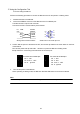
4.3. Example of Extracting Measured Data This shows how to count bit numbers in the MX118. With Big Endian, from the start of the data field, starting with the msb of the MSB, bit numbers decrease in units of bytes or bits from left to right. The first bit number of the data field is always 63. For Llittle Endian, from the start of the data field, starting with the msb of the LSB, bit numbers increase in units of bits from right to left, and in units of bytes from left to right.
Data Field Length = 8 Bytes For Big Endian: Available start bit position settings: 0–(Bit Length-1) 63・・・・・・56 55・・・・・・48 47・・・・・・40 39・・・・・・32 31・・・・・・24 23・・・・・・16 15・・・・・・8 7・・・・・・0 Byte 7 Byte 6 Byte 5 Byte 4 Byte 3 Byte 2 Byte 1 Byte 0 bit lsb For Little Endian: Available start bit position settings: 0–(64-Bit Length) 7・・・・・・0 15・・・・・・8 23・・・・・・16 31・・・・・・24 39・・・・・・32 47・・・・・・40 55・・・・・・48 63・・・・・・56 Byte 0 Byte 1 Byte 2 Byte 3 Byte 4 Byte 5 Byte 6 Byte 7 bit lsb Th