
Instruction Manual


5-26
IM MW100-01E
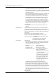
Values per Modbus Registers (Communication input channel data)
The main module handles data from the communication input channels as type Float.
The Modbus register values of these data are shown in the table below.
Comm. Input
Channel Data
(Float)(x)
Value (y)
per Modbus Register
Float Int 32
min = –2,147,483,648
max = 2,147,483,647
Int 16
min = –32,768
max = 32,767
Bit
*1
+Inf +Inf max max 0
–Inf –Inf min min 0
NaN NaN max max 0
Valid Data (physical qty.) Data (integer)
*2
y = integral portion of x (min ≤ x ≤ max)
y= min (x < min)
y = max (x > max)
Data (integer)
*2
y = integral portion of x (min ≤ x ≤ max)
y= min (x < min)
y = max (x > max)
0, 1
*3
*1 The value of the bit alone is insufficient to determine whether it is a special value. Mode (18000’s, 38000’s) and other
information must also be used to determine whether it is a special value or other value.
*2 The value is read in with the values after the decimal place removed. For example, if the value stored in a communication
input channel is 56.78, the value read in under the Word type is 56. If the value stored in a communication input channel is
–12.34, the value read in under the Word type is –12.
*3 The value is 0 (Off) when the corresponding communication input data is zero, and 1 (On) when the data is not zero.
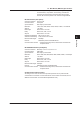
Modbus error response: The main unit returns the following error codes to the master
instrument.
Code Function Operation
1 Function code invalid Requested non-supported function
2 Invalid register number Attempted to read/write registers for which no
corresponding channels could be found.
3 Invalid number of registers
The specified number of registers was zero.
7 Could not be executed Attempted to read MATH registers from an
instrument without the MATH function option.
However, there is no response in the following cases.
• CRC Error
• Errors other than in above table.
5.2 Main Module (MW100-E) Specifications