User’s Manual MW100 Data Acquisition Unit IM MW100-01E 4th Edition
Thank you for purchasing the MW100 Data Acquisition Unit. This user’s manual contains useful information about the instrument’s functions, installation and wiring procedures, operating procedures, and handling precautions. To ensure correct use, please read this manual thoroughly before beginning operation. The following manuals relating to the MW100 Data Acquisition Unit are provided in addition to this one. Read them along with this manual.
Trademarks Revisions ii • DAQMASTER is a registered trademarks of Yokogawa Electric Corporation. • Microsoft and Windows are registered trademarks or trademarks of Microsoft Corporation in the United States and/or other countries. • Adobe and Acrobat are registered trademarks or trademarks of Adobe Systems Incorporated. • Company and product names that appear in this manual are registered trademarks or trademarks of their respective holders.
Safety Precautions About This Manual • Please pass this manual to the end user. • Read this manual thoroughly and have a clear understanding of the product before operation. • This manual explains the functions of the product. It does not guarantee that the product will suit a particular purpose of the user. • Under absolutely no circumstances may the contents of this manual be transcribed or copied, in part or in whole, without permission.
Safety Precautions Warn WARNING Use the Correct Power Supply Ensure that the source voltage matches the voltage of the power supply before turning ON the power. Connect the Protective Grounding Terminal Make sure to connect the protective grounding to prevent electric shock before turning ON the power. Do Not Impair the Protective Grounding Never cut off the internal or external protective earth wire or disconnect the wiring of the protective earth terminal.
Conventions Used in This Manual Unit k K Denotes 1000. Denotes 1024. Example: 5 KB (file size) Safety Markings The following markings are used in this manual. Refer to corresponding location on the instrument. This symbol appears on dangerous locations on the instrument which require special instructions for proper handling or use. The same symbol appears in the corresponding place in the manual to identify those instructions.
Contents Safety Precautions........................................................................................................................ iii Conventions Used in This Manual..................................................................................................v Chapter 1 Explanation of Functions 1.1 1.2 1.3 1.4 1.5 vi System Overview............................................................................................................ 1-1 MW100 Data Acquisition Unit........
Contents 1.6 1.7 1.8 1.9 1.10 1.11 1.12 1.13 IM MW100-01E Functions of the 30-CH, Medium-Speed DCV/TC/DI Input Module.............................. 1-41 Measurement Input Types............................................................................................. 1-41 Measurement Range..................................................................................................... 1-41 Measurement Interval, Integration Time, and Filter......................................................
Contents 1.14 1.15 1.16 Chapter 2 Installation and Wiring 2.1 2.2 2.3 2.4 viii Functions of the 10-CH, Medium-Speed Digital Output Module................................... 1-59 Output Types................................................................................................................. 1-59 Output Update Interval.................................................................................................. 1-59 Relay Excitation State / Hold Operation.............................
Contents 2.5 2.6 2.7 2.8 2.9 2.10 Chapter 3 Setting and Data acquisition 3.1 3.2 3.3 3.4 IM MW100-01E Connecting the Power Supply and Turning the Power Switch ON and OFF................ 2-20 Connections with the Power Cord (Power Supply and Power Cord Suffix Code -1c*) 2-20 Wiring the Power Supply Terminal (Power Supply and Power Cord Suffix Code -1W) 2-21 Wiring the Power Supply Terminal (When the Suffix Code of the Power Supply/Cord Is -2c* or -3W).............................................
Contents 3.5 3.6 3.7 3.8 3.9 3.10 3.11 3.12 3.13 3.14 3.15 3.16 Setting Measurement Conditions (Measurement Channel Settings)............................ 3-24 Measurement Channel Settings.................................................................................... 3-24 Global Channel Settings............................................................................................... 3-26 Scale Input Methods...............................................................................
Contents Chapter 4 Troubleshooting and Maintenance 4.1 4.2 4.3 4.4 4.5 4.6 4.7 Chapter 5 Specification 5.1 5.2 5.3 IM MW100-01E Error Display on the 7-Segment LED and Corrective Actions......................................... 4-1 Errors upon Startup......................................................................................................... 4-1 System Errors.................................................................................................................
Contents 5.4 5.5 5.6 5.7 5.8 5.9 5.10 5.11 5.12 5.13 5.14 xii 4-CH, High-Speed Universal Input Module (MX110-UNV-H04) Specifications............. 5-35 Effects of Operating Conditions.................................................................................... 5-38 General Specifications.................................................................................................. 5-38 External Dimensions...................................................................................
Contents Appendix Appendix 1 Appendix 2 Appendix 3 Appendix 4 Appendix 5 Appendix 6 Appendix 7 Appendix 8 Supported Characters...................................................................................... App-1 Setting Data Communication That Uses Modbus Protocol.............................. App-2 Setup Procedure.............................................................................................. App-2 Example System...................................................................
Chapter 1 Explanation of Functions 1.1 System Overview 1 The MW100 Data Acquisition Unit consists of a main module equipped with an Ethernet port, I/O modules for input and output of signals (these are the same as those for the MX100 Data Acquisition Unit), and a base plate on which the first two items are mounted. The main module comes with an HTTP server function, allowing users to easily enter settings, acquire data, and monitor measured data from a PC using a browser.
1.1 System Overview One-to-N Connection with a PC This is an example of a configuration suitable for relatively large scale data acquisition tasks. Connections can be made via Ethernet or RS-422A/485.
1.1 System Overview 1 One-to-N Connection with the PC Explanation of Functions This is an example in which multiple PCs are connected to the MW100 for performing data monitoring. 2 PC PC PC 3 4 Hub 5 MW100 App MW100 Data Acquisition Unit Connecting to Modbus Devices Index This is an example of configuration of a system with connections to Modbus devices.
1.1 System Overview Main Module The main module is equipped with power supply connectors, a power switch, Ethernet ports, and other devices facilitating supply of power to and control of the input/output modules, and connection to networks. It also has Start and Stop keys, meaning that since data can be saved to a CF card, data can be acquired offline. Data acquisition via serial communication is also possible by adding the RS-232 or RS-422A/485 serial communication option.
1.
1.
1.
1.1 System Overview PC Software The MW100 Data Acquisition Unit comes with the MW100 Viewer software program that allows users to view measured data acquired by the MW100. MW100 Viewer consists of the three software components described below. For a detailed description of the functions of these software components, see the MW100 Viewer Software User’s Manual (IM MW180-01E).
1.2 MW100 Operation Guide 1 Operations on the PC Operations on the MW100 Section 2.2 and 2.3 Instal the MW100 and attaching the main module Section 3.2 Set up communication Section 3.3 Section 2.4 Wire the input/ output modules Configure the system Section 2.6 to 2.8 See the Installation Connect and Connection communication Guide cables (IM MX100-72E). Section 2.5 Connect the power cord Section 2.5 Turn ON the power switch 2 Section X.X indicates the referred sections in this manual.
1.3 Functions of the Main Module The main module is the central component of the MW100 Data Acquisition Unit. Names and Functions of Parts Communication status LED Ethernet port Check the communication status Top: LINK LED Illuminates orange when ready for communication Bottom: ACT LED Blinks green when packets are sent/received Used for main unit settings and network connections (see 2.6, “Connecting an Ethernet Cable,” or 3.2, “Connecting to the MW100.
1.3 Functions of the Main Module 1 Switches and Keys Explanation of Functions The MW100 has the following switches and keys. Some are included with options. • Start and Stop keys • User function key 1 • User function key 2 • Dip switch 1 • Dip switch 2 • Terminator switch (/C3 option) • Power switch 2 3 User Function Keys 4 Actions set up using the Event/Action function can be executed by pressing the user function keys on the front panel of the MW100. The keys are assigned as follows by default.
1.3 Functions of the Main Module Connectors The MW100 can come with the following connectors. The actually-installed connectors depend on the power supply input section specifications and options.
1.3 Functions of the Main Module 2 For the handling of the CF card, see “Handling of the CF Card” in section 2.10. For CF card replacement, see “Saving Data to the CF Card” in this section. 3 • Access Forewarning to the CF Card When saving measured, computed, or thinned data, the dots blink before accessing of the CF card. This indication starts 10 seconds before the access. If you see this indication, quickly finish the insertion or removal of the CF card.
1.3 Functions of the Main Module Measurement Measured data sampled at certain intervals is acquired by the various input modules. Acquired data is stored in internal memory. During recording, acquired data is saved to the CF card according to the settings. In addition, if an alarm occurs or if the main module receives output commands sent from the PC, the main module generates signal output instructions to the output modules.
1.
1.3 Functions of the Main Module Range Over When the MW100 detects a range over (see below) on a measurement or MATH channel, “+Over” or “–Over” is displayed. • Measurement channel range over • During DC voltage input, strain input, and resistance (20 Ω, 200 Ω, etc.), a range over is detected if the value that is measured on a measurement channel is outside of the measurable range by more than ±5%. For example, when the measurement range is 2 V, the measurable range is –2.0000 to 2.0000 V.
1.3 Functions of the Main Module 1 Alarms Type Notation Actions Upper limit alarm H Generates an alarm when the measured value exceeds the alarm value. Lower limit alarm L Generates an alarm when the measured value falls below the alarm value. Differential upper limit alarm DH Generates an alarm when the difference between (during differential computation) the measured values of two alarms exceeds the alarm value.
1.3 Functions of the Main Module Upper Limit on Rate-of-Change/ Lower Limit on Rate-of-Change Alarm The rate of change of the measured values is checked over the rate-of-change detection interval. An alarm occurs if the rate of change of the measured value in the rising or falling direction exceeds the specified value.
1.3 Functions of the Main Module 1 Event Action Function Event Types The following types of events are available. Some items may not be available depending on the options installed.
1.3 Functions of the Main Module Action Notation Write free message Free Message Write message on specified number Message1 Message2 Message3 Message4 Message5 Save specified file*2 File Save *2 File Load Load specified file Perform manual sample*1 Manual Sample Divide manual sample file*1 Manual Divide Detection Method Edge Level *1 Cannot be selected when the event is Recording start. *2 Can be selected when the event is User function key.
1.3 Functions of the Main Module 1 Event detection methods* Notation Description Edge Edge Edge event Level Level Level event Explanation of Functions Method 2 * The following limitations exist on the setting. You cannot set the same action type for Edge and Level. The following action types are considered the same. Memory Start and Memory Stop MATH Start and MATH Stop Flag with the same flag number • You cannot set the same action type for different levels.
1.3 Functions of the Main Module Measurement, Computation, and Thinning Recording Operations Recording Start/Stop You can start or stop recording to the CF card using the Start/Stop key, even action function, communication command, or monitor screen. Recording Start Action The operations for starting the recording to the CF card are given below. The recording start action is set to Direct for thinning recording. Type Notation Operation None Off Does not record.
1.3 Functions of the Main Module Start Trigger condition met 1 Stop Explanation of Functions Single 2 Time (s) File Stop recording after creating a single file Start Trigger condition met 3 Trigger condition met Fullstop* Rotate* 4 Time (s) File File Trigger-wait status * The condition for stopping the recording when set to Fullstop and the condition for deleting the file when set to Rotate is the same as the condition when the recording start action is set to Direct.
1.3 Functions of the Main Module Manual Sample Function When you perform a manual sample, the measured and computed data from specified channels are written to the manual sample file. When the CF card is inserted, the data is written to the manual sample file each time you perform the manual sample. If the card is not inserted, the data is stored in internal memory and written to the CF card the next time it is inserted. A manual sample function can be carried out when in Measurement mode.
1.3 Functions of the Main Module 1 Saving Data to the CF Card Measured data, computed data, thinned data, recording logs, alarm summaries, manual sample data, report data, and settings can be saved on the CF card. • Folder Structure The structure of the data save folder is as shown below.
1.3 Functions of the Main Module Saving Measured Data and Computed Data Files can be created for every measurement group. An individual file is created for computed data. For each measurement group, you can select whether or not to perform the save operation. The table below shows the approximate interval over which data can be saved to the CF card when one measurement interval is used. Save Channel Measurement Interval Capacity of the CF Card 128 MB 512 MB 10 ch 8.8 hours 3.
1.3 Functions of the Main Module Replacing the CF Card While Recording For a description of the CF card access indicator, see “Displays” in this section. For a description of the time when data is written to the CF card, see appendix 8, “Saving Data to the CF Card.” 1 Explanation of Functions You can replace the CF card while the recording is in progress. Replace the CF card quickly while the access indicator (in-progress display) to the CF card is not ON.
1.3 Functions of the Main Module Communication Specifications The MW100 can communicate with external devices using its Ethernet or serial communication port. Login Function This function ensures that only previously registered users can obtain access when communicating with the MW100. For instructions, see section 3.2, “Communication Settings.
1.3 Functions of the Main Module 2 3 Ethernet 4 MW100 DX2000 (with the /MC1 option) (Client) 1 Explanation of Functions • Modbus Server Function Modbus clients connect to an MW100 acting as the Modbus Server, and read from or write to its internal registers. Measured data and alarm statuses from measurement channels, measured data and alarm statuses from MATH channels, data from communication input channels, and time information are stored in the MW100’s registers.
1.3 Functions of the Main Module E-Mail Function Notification can be made of alarm occurrences and creation of data files by e-mail. Two recipient locations can be specified. Multiple addresses can be specified for each recipient location. For details about e-mail contents, see chapter 5, “Specifications.” E-Mail Types The following types of e-mail can be generated.
1.3 Functions of the Main Module 1 Subject E-Mail Type Alarm notification Report notification File creation notification Notification of remaining space on media Notification of power ON System error notification Fixed time report Test Explanation of Functions The e-mail transmission type is added to the subject. A user-specified string can be added to the transmission type in the subject. The following subject topics are available.
1.3 Functions of the Main Module RS-422A/485 Communication (/C3 Option) In a multi-drop, four-wire configuration, up to thirty-two units can be connected. A dedicated protocol and the ModbusRTU protocol are supported. Using communication commands, you can send and receive settings, and measured and computed values. • Modbus Master Function (/M1 Option) The MW100 can connect to a Modbus slave device and load measured data. The operation is the same as the Modbus client function.
1.3 Functions of the Main Module Log Information 2 Saving the Recording Log File While recording is stopped, information related to operation of the CF card and power ON/OFF status is saved in text format to a log file with the name RECORDLG.TXT. For information about log statuses and messages, see the MW100 Communication Command Manual (IM MW100-17E).
1.3 Functions of the Main Module Saving Alarm Summaries When the recording stop action is activated, alarm summary information is saved in text format to a log file named ALARMLG.TXT. Example of an Alarm Summary Date EA 07/10/25 07/10/25 07/10/25 07/10/25 07/10/25 07/10/25 07/10/25 07/10/25 07/10/25 07/10/25 07/10/25 EN Time Channel Alarm status* 10:12:13.000 11:14:12.000 11:14:12.000 11:14:13.000 11:14:21.000 11:14:36.000 11:14:36.000 11:14:54.000 11:15:18.000 11:15:22.000 11:15:25.
1.4 Functions of the 4-CH, High-Speed Universal Input Module 1 2 3 Terminal cover 4 Input terminal (clamp terminal) 5 Measurement Input Types Measurement Input Type Notation Do not measure SKIP DC voltage VOLT Thermocouple TC Resistance temperature detector RTD DI DI Remote RJC RRJC App Index Measurement Range DC Voltage Measurement Range Notation Rated Measurement Range 20 mV 20 mV –20.000 to 20.000 mV 60 mV 60 mV –60.00 to 60.00 mV 200 mV 200 mV –200.00 to 200.
1.4 Functions of the 4-CH, High-Speed Universal Input Module Thermocouple (cont.) Measurement Range Notation Rated Measurement Range Type-U U –200.0 to 400.0°C KPvsAu7Fe KPvsAu7Fe 0.0 to 300.0K PLATINEL PLATINEL 0.0 to 1400.0°C PR40-20 PR40-20 0.0 to 1900.0°C NiNiMo NiNiMo 0.0 to 1310.0°C WRe3-25 WRe3-25 0.0 to 2400.0°C W/WRe26 WWRe26 0.0 to 2400.0°C Type-N (AWG14) N14 0.0 to 1300.0°C Type-XK GOST XK –200.0 to 600.
1.4 Functions of the 4-CH, High-Speed Universal Input Module 1 Resistance Temperature Detector (2 mA, cont.) Notation Rated Measurement Range Pt100 (high noise resistance) Pt100-2R –200.0 to 250.0°C JPt100 (high noise resistance) JPt100-2R –200.0 to 250.0°C Cu100 GOST Cu100G –200.0 to 200.0°C Cu50 GOST Cu50G –200.0 to 200.0°C Cu10 GOST Cu10G –200.0 to 200.0°C Explanation of Functions Measurement Range 2 3 DI Measurement Range Notation Rated Measurement Range LEVEL LEVEL Vth=2.
1.5 Functions of the 10-CH, Medium-Speed Universal Input Module This module allows up to ten inputs of DC voltage, thermocouple, 3-wire RTD, and digital input (DI) at a minimum measurement interval of 100 ms.
1.5 Functions of the 10-CH, Medium-Speed Universal Input Module 1 Thermocouple (cont.) Notation Rated Measurement Range Type-L L –200.0 to 900.0°C Type-U U –200.0 to 400.0°C KPvsAu7Fe KPvsAu7Fe 0.0 to 300.0 K PLATINEL PLATINEL 0.0 to 1400.0°C PR40-20 PR40-20 0.0 to 1900.0°C NiNiMo NiNiMo 0.0 to 1310.0°C WRe3-25 WRe3-25 0.0 to 2400.0°C W/WRe26 WWRe26 0.0 to 2400.0°C Type-N (AWG14) N14 0.0 to 1300.0°C Type-XK GOST XK –200.0 to 600.
1.5 Functions of the 10-CH, Medium-Speed Universal Input Module DI Measurement Range Notation Rated Measurement Range LEVEL LEVEL Vth=2.4 V Contact input CONTACT 1 kΩ or less, ON, 100 kΩ or less, OFF (shunt capacitance: 0.01 µF or less) Measurement Interval, Integration Time, and Filter You can select from the following measurement intervals for this module.
1.6 Functions of the 30-CH, Medium-Speed DCV/ TC/DI Input Module 1 MX110-VTD-L30 MX110-VTD-L30/H3 Explanation of Functions This module allows up to thirty inputs of DC voltage, thermocouple, and digital input (DI) at a shortest measurement interval of 500 ms. It takes up three modules worth of space when attaching to the base plate.
1.6 Functions of the 30-CH, Medium-Speed DCV/TC/DI Input Module Thermocouple (cont.) Measurement Range Type-N Type-W Type-L Type-U KPvsAu7Fe PLATINEL PR40-20 NiNiMo WRe3-25 W/WRe26 Type-N (AWG14) Type-XK GOST DI Measurement Range LEVEL Contact input Notation N W L U KPvsAu7Fe PLATINEL PR40-20 NiNiMo WRe3-25 WWRe26 N14 XK Rated Measurement Range 0.0 to 1300.0°C 0.0 to 2315.0°C –200.0 to 900.0°C –200.0 to 400.0°C 0.0 to 300.0 K 0.0 to 1400.0°C 0.0 to 1900.0°C 0.0 to 1310.0°C 0.0 to 2400.0°C 0.0 to 2400.
1.7 Functions of the 6-CH, Medium-Speed FourWire RTD Resistance Input Module 1 2 3 Terminal cover 4 Input terminal (clamp terminal) Measurement Input Types Measurement Input Type Notation No measurement SKIP DC voltage VOLT Resistance temperature detector RTD Resistance OHM DI DI 5 App Index Measurement Range DC Voltage Measurement Range Notation Rated Measurement Range 20 mV 20 mV –20.000 to 20.000 mV 60 mV 60 mV –60.00 to 60.00 mV 200 mV 200 mV –200.00 to 200.
1.7 Functions of the 6-CH, Medium-Speed Four-Wire RTD Resistance Input Module Resistance Temperature Detector (1 mA, cont.) Measurement Range Notation Rated Measurement Range J263B J263B 0.0 to 300.0K Cu10 at 20°C alpha=0.00392 Cu10a392 –200.0 to 300.0°C Cu10 at 20°C alpha=0.00393 Cu10a393 –200.0 to 300.0°C Cu25 at 0°C alpha=0.00425 Cu25 –200.0 to 300.0°C Cu53 at 0°C alpha=0.00426035 Cu53 –50.0 to 150.0°C Cu100 at 0°C alpha=0.00425 Cu100 –50.0 to 150.
1.8 Functions of the 4-CH, Medium-Speed Strain Input Module 1 Explanation of Functions This module allows up to four inputs of measurement from strain gauges and strain gauge type sensors at a minimum measurement interval of 100 ms.
1.8 Functions of the 4-CH, Medium-Speed Strain Input Module Initial Balancing (Unbalance Adjustment) When configuring a bridge circuit with a strain gauge, due to the slight deviation in resistance of the strain gauge, the bridge circuit will not necessarily be balanced even if the strain of the circuit under test is zero, and the measured value may not be zero (the value in such cases is called the initial unbalanced value).
1.8 Functions of the 4-CH, Medium-Speed Strain Input Module Scaling Settings of the Strain Gauge Type Sensor The following gives two examples, one when the rated input and output are known, and one when the calibration coefficient is known. (Hereinafter, µ-strain will be expressed as µSTR). Explanation of Functions This is an explanation of scaling settings used to measure physical quantities such as load and length using a strain gauge type sensor.
1.8 Functions of the 4-CH, Medium-Speed Strain Input Module When the Calibration Coefficient is Known An example using a displacement gauge provides an explanation. • Rated input 20 mm • Calibration coefficient 0.003998 mm / (1 µV/V) Basically, if you can convert the calibration coefficient to the rated output mentioned in “When Rated Input and Rated Output Are Known,” the previous equation can be used. Using equation 1, 1 µV/V = 0.001 mV/V = 0.
1.9 Functions of the 10-CH, Pulse Input Module 1 Explanation of Functions This module has ten inputs for integration of numbers of pulses.
1.9 Functions of the 10-CH, Pulse Input Module Input Range Maximum speed: 10000 pulses/s Minimum input pulse width: 40 μs Input Threshold Level LEVEL Counts when changing from 1 V or less to 3 V or more Contact input Count upon change from contact open to contact close Contact open: 100 kΩ or more Contact close: 100 Ω or less Filter Anti-Noise Filter The integral time and types of filters applied vary depending on the measurement interval. For information on filters, see section 2.
1.10 Functions of the 10-CH, High-Speed Digital Input Module 1 Explanation of Functions The “-D05” module is equipped with ten inputs for measurement of non-voltage contact, open collector, and 5 V logic inputs at a minimum measurement interval of 10 ms. The “-D24” module is equipped with ten inputs and measures 24-V logic inputs at a minimum measurement interval of 10 ms.
1.11 Functions of the 8-CH, Medium-Speed Analog Output Module The module has eight outputs for voltage or current. An external power source (24 V) is required for current output. For voltage output only, an external power source is not required.
1.12 Functions of the 8-CH, Medium-Speed PWM Output Module 1 Explanation of Functions This module has eight outputs for pulse wave duty. A certain duty pulse waveform is output according to the specified pulse interval. A pulse interval can be set for each channel.
1.13 Operation of the 8-CH Medium-Speed Analog Output Module and the 8-CH Medium Speed PWM Output Module The following describes the output operation of the analog and PWM output modules. Output upon Startup, Error Occurrence, and Stopping* * Firmware version R3.03 or later Output Selection Notation Actions Hold previous value Last Holds the last value output. Output preset value Preset Outputs an arbitrarily specified output value.
1.13 Operation of the 8-CH Medium-Speed Analog Output Module and the 8-CH Medium Speed PWM Output Module 1 Output Operation through Setting Changes (Common) Output Operation Setting changes for operation*1 Prev. value held → preset value Outputs the preset value the on startup next time the power is turned ON Preset value → hold prev.
1.
1.
1.
This module has ten contact signal outputs that are based on alarm output settings and output settings from the PC. 1 Explanation of Functions 1.14 Functions of the 10-CH, Medium-Speed Digital Output Module 2 3 Terminal cover 4 Output terminal (clamp terminal) 5 Output Types The following types (output factors) are available. Type Alarm Manual Notation Alarm Comm.
1.14 Functions of the 10-CH, Medium-Speed Digital Output Module Also, when a condition in which alarm output must be cleared arises, you can select whether to turn output relays OFF (Non-hold), or leave them ON until an output clear command (alarm ACK) appears (Hold). Hold operation Notation Description Hold On Maintains relay output even after relay output is cancelled. Non-Hold Off Does not maintain relay output when relay output is cancelled (normal operation).
1.14 Functions of the 10-CH, Medium-Speed Digital Output Module 1 Preset Output upon Error (Firmware version R3.03 or later) Output Off Open Close Notation Off Open Close Description No forced transition to Open/Close upon error. Relay output Open (De-energize) upon error. Relay output Close (Energize) upon error. Explanation of Functions The following types are available. 2 • The following conditions are required when the DO preset setting is enabled.
1.15 MATH Function (/M1 Option) Overview of the MATH Function Results are computed by expressions using constants, operators, and functions. Computed data from computed results can be displayed or recorded (saved). MATH allows you to determine the average/maximum/minimum of a specified channel on a specified date/time, or output events (start/stop record, reset time, etc.) under specified conditions.
1.
1.15 MATH Function (/M1 Option) TLOG Functions*1 The TLOG computation computes the maximum, minimum, maximum-minimum, integral, average, and pulse integral of the specified channel. One function can be used per expression. Type Operators Maximum value TLOG.MAX() TLOG.MAX(001) Example Finds max value of measured values on ch 001. Explanation Minimum value TLOG.MIN() TLOG.MIN(002) Finds min value of measured values on ch 002. Maximum value to minimum value TLOG.P-P() TLOG.
1.15 MATH Function (/M1 Option) Order of Operations in Expressions Type (High precedence) Arithmetic, TLOG, CLOG functions, and Bit output Conditional expressions Exponentiation Logical negation Multiplication and division Addition and subtraction Relational operation Equivalence Logical product Logical sum, exclusive OR (Low precedence) Operators ABS(), SQR(), LOG(), EXP(), TLOG.MAX(), TLOG.MIN(), TLOG.P-P(), TLOG.SUM(), TLOG.AVE(), TLOG.PSUM(), CLOG.MAX(), CLOG.MIN(), CLOG.P-P(), CLOG.
1.15 MATH Function (/M1 Option) Program Channels Up to thirty-two inputs of broken line data can be included in expressions. Multiple points can be set for the time from the start point and the output value at that point. Specified points are linked with a straight line, the value of Y at the elapsed time X is output. There is Single, in which one cycle is executed, and Repeat in which execution repeats.
1.15 MATH Function (/M1 Option) Group Reset Math Groups Specifies multiple channels from among Math channels 1 through 60. Up to seven groups can be set. Math groups are used with group reset. 1 Explanation of Functions Clears all MATH channel data (including MATH alarms) per the Event/Action function or requests from communication commands. If this request occurs during a computation, it is executed on the next computation interval and computation starts.
1.15 MATH Function (/M1 Option) Handling Units in Computations In computations, computed values (measured and computed data) are handled as numbers without units. Also, they are unrelated to the math channel units. Example: Expression = 001 + 002 + K01 001 (measurement ch 1) = 20 mV, 002 (measurement ch 2) = 30 V, K01 (math constant) = 10 Given the above, the computed result is 60. Alarm Level You can implement alarm actions based on the computed data. Four levels can be set per channel.
1.15 MATH Function (/M1 Option) Processing Computed Results with Abnormal Input Values or Overflow Values Explanation of Functions You can select the computed result when an error occurs on the reference channel (measurement or MATH channel) of a MATH channel. For processing of computed results, see “MATH Operation Settings” in section 3.4. 2 MATH Operation You can select the computed data when the computed result is an error.
1.
1.15 MATH Function (/M1 Option) 1 TLOG Time Scale Integration Units Notation Explanation No time scale Off Σ (data)*1 Every second /sec Σ (data)/(Number of times of computing per second.) Σ (data)/(Number of times of computing per minute.) Every minute /min Every hour /hour Σ (data)/(Number of times of computing per hour.) Every day*2 /day Σ (data)/(Number of times of computing per day.) Explanation of Functions You can select the sum scale for the TLOG.SUM computation.
1.16 Report Function (/M3 Option) The maximum, minimum, average, integral, and instantaneous values of the specified measurement or MATH channels (up to 60 ch) can be written to the following report files.
1.16 Report Function (/M3 Option) Report Measurement Interval 2 Sum Scale of the Integral Value You can select the unit time (formula) for the integral value. Unit time and units can be specified for each channel.
1.16 Report Function (/M3 Option) Processing Reports with Abnormal Input Values or Overflow Values You can select how reports are processed when an error occurs on the channel (measurement or MATH channel) for which a report is created. For report processing during abnormalities, see “Report Operation Settings 1” in section 3.12.
Chapter 2 2.1 Installation and Wiring Handling Precautions 1 This section describes the precautions to be taken when using the MW100. Please read before using this product. IM MW100-01E 2-1 Installation and Wiring • If you are using this instrument for the first time, make sure to thoroughly read the safety precautions given on pages iii and iv. • Do not remove the case. For internal inspection or adjustment, contact your nearest YOKOGAWA dealer. • Do not place objects on top of the instrument.
2.2 Installation Installation Location Install the instrument indoors in the following locations. • In temperatures of –20 to 60°C If the ambient temperature is –20 to 40°C, place the instrument in a location where the humidity is 20 to 80% RH. For 40 to 50°C, the humidity should be 10 to 50%. For 50 to 60°C, the humidity should be 5 to 30%. However, no condensation should be present. Also note that the temperature range of certain modules is –20 to 50°C.
2.2 Installation Placing on a Desktop or on the Floor Since each module has feet you can attach the necessary modules to the base plate allowing the unit to be placed vertically. For the procedure for attaching the modules, see the next page. 1 2 Installation and Wiring 3 4 5 Feet Functional ground terminal screw App Attaching to DIN Rails By attaching DIN rail mounting brackets to the base plate as in the figure below, you can rack-mount or panel-mount the MW100 Data Acquisition Unit.
2.3 Attaching the Modules WARNING To prevent electric shock and instrument breakdown, do not connect the power supply to the main module when attaching modules. Preparing the Base Plate The accessory brackets are attached in order to attach the MW100 main module to the base plate. Remove the base block bracket Attach the bracket that came with the MW100 Attachment Procedure 1. Check that the power supply is not connected to the main module. 2.
2.3 Attaching the Modules 1 Attachment Positions and Channel Numbers Channel numbers are recognized as follows: • Browser monitor and commands Channel numbers within units. Example: CH001 • MW100 Viewer software Unit number + Channel number within units.
2.4 Connecting Signal Wires Terminal Arrangement Markings on the Terminal Cover Characters indicating the terminal function and a terminal symbol indicating the type of signal to be input/output to each terminal are written on the back of the terminal cover of each I/O module. For information on wiring of corresponding terminal signals, see the wiring procedures in this section. The 4-CH Medium-Speed Strain Module (-NDI) does not have a terminal cover.
2.4 Connecting Signal Wires 1 Attaching and Removing the Terminal Block The I/O terminals of the modules in the figure below can be removed. The terminals of the 30-CH, Medium-Speed DCV/TC/DI Input Module (MX110-VTD-L30) cannot be removed. The terminal cover can be removed by pressing backward with the cover lifted up.
2.4 Connecting Signal Wires Attaching the Plate with Screw Terminal and Plate with Clamp Terminals for Current A screw terminal plate (model 772080, sold separately) can be attached to the 10-CH Medium Speed Universal Input Module, the 10-CH Pulse Input Module, and the 10-CH, High Speed Digital Input Module. In addition, the dedicated plate with clamp terminals for current (model 772081/772082/772083, sold separately) can be attached to the 10-CH Medium Speed Universal Input Module.
2.
2.4 Connecting Signal Wires CAUTION • If a large pulling force is applied to the input/output signal wires connected to the MW100, the terminal or signal wire may break. To prevent this from happening, secure all the wiring cables to the installation panel. • Do not apply a voltage exceeding the value indicated below to the input terminals of the universal input modules. Doing so can damage the modules.
2.4 Connecting Signal Wires 1 • Do not apply a voltage exceeding the value indicated below to the input terminals of the 10-CH, High-Speed Digital Input Module and the output terminals of the 10-CH, Medium-Speed Digital Output Module. Doing so can damage the modules.
2.4 Connecting Signal Wires Wiring Procedures 1. 2. 3. 4. Turn OFF the power to the instrument. Loosen the terminal cover attachment screw and lift up the terminal cover. Connect the signal wires to the terminals. Return the terminal cover to the original position and secure it with the screw. The appropriate screw tightening torque is 0.6 N·m.
2.4 Connecting Signal Wires 1 Wiring the 4-Wire RTD Resistance Input Module • DC voltage input/DI (contact) input • RTD input, resistance input Voltage I B DC voltage Input C B Contact C Nothing connected to the I or C terminal 2 A Resistance per lead wire of 10 Ω or less • DC current input I B C Terminal type: Applicable wire size: 3 4 + DC current input – Shunt resistor Example: For 4 to 20 mA input, shut resistance values should be 250 Ω ±0.1%.
2.4 Connecting Signal Wires • 1 Gauge 3 Wire Method R r Rg R R r r e E R: fixed resistance r: resistance value of lead wire Rg: resistance value of strain gauge e: output voltage from bridge E: voltage applied to bridge -NDI Bridge head (701955 or 701956) 1 2 3 4 5 6 7 8 Rg -B12, -B35 Setting switch A(+V) No.1 No.2 No.3 No.4 No.5 Rg B(L) C(-V) ON OFF D( H) ON OFF Setting switch SW No.1 No.2 No.3 No.4 No.
2.4 Connecting Signal Wires 1 • Opposing 2 Gauge Method R Rg1 Rg2 e R Rg2 E -NDI -B12, -B35 Rg1 A(+V) No.1 No.2 No.3 No.4 No.5 Rg1 B( L) C(-V) Rg2 D( H) ON OFF Rg2 Setting switch No.1 No.2 No.3 No.4 No.5 ON OFF ON OFF ON 3 Bridge head (701955 or 701956) Setting switch 1 2 3 4 5 6 7 8 4 5 ON OFF SW App 1 2 3 4 5 SW1 SW2 SW3 SW4 SW5 ON OFF ON ON OFF • Opposing 2 Gauge 3 Wire Method R r Rg1 r r r r Rg2 Rg1 e R Rg2 r E -B12, -B35 Cannot be connected. Use -NDI.
2.4 Connecting Signal Wires • 4 Gauge Method Rg4 Rg3 R: fixed resistance r: resistance value of lead wire Rg: resistance value of strain gauge e: output voltage from bridge E: voltage applied to bridge e Rg2 Rg1 E Rg1, Rg3 Rg1 Rg2, Rg4 Rg2 Rg1 Rg3 Rg3 Rg4 Rg1, Rg2 Rg3, Rg4 -B12, -B35 Setting switch No.1 No.2 No.3 No.4 No.5 OFF A(+V) Rg1 B( L) Rg2 C(-V) Rg3 D( H) Rg4 ON No.1 No.2 No.3 No.4 No.
2.4 Connecting Signal Wires 1 Wiring the Pulse Input Module and Digital Input Module Note • • Wiring the Pulse Input and Digital Input (-D05) • Contact input • Transistor input • 5-V logic input 5V 2 Installation and Wiring With the pulse input module and digital input module, the (–) terminal and unassigned terminals on all channels are shorted internally.
2.4 Connecting Signal Wires Wiring with the Analog Output Module External power supply Voltage + 24 V power supply Vext Current V+ Load (when using current output) I+ Load Direction of current CAUTION Two power supply terminals are connected internally. Therefore, do not connect a separate external power supply to them. Fire can result.
2.4 Connecting Signal Wires 1 Wiring with the Digital Output Module NO C 250 VDC/0.1 A, 250 VAC/2 A, or 30 VDC/2 A (resistance load) 2 Installation and Wiring Main Output Specifications Contact mode: Contact capacity: Terminal type: Applicable wire size: 3 A contact (SPST) 250 VDC/0.1 A, 250 VAC/2 A, or 30 VDC/2 A (resistance load) Clamp, attached and removed in units of 5 channels 2 0.08 to 2.
2.5 Connecting the Power Supply and Turning the Power Switch ON and OFF Connections with the Power Cord (Power Supply and Power Cord Suffix Code -1c*) * c is D, F, R, Q, or H. WARNING • To prevent the possibility of electric shock when wiring, confirm that the power supply source is turned OFF. • To prevent shock or fires, only use the power cord supplied by Yokogawa together with the MW100 Data Acquisition Unit. • Make sure to perform protective earth grounding to prevent electric shock.
2.5 Connecting the Power Supply and Turning the Power Switch ON and OFF Wiring the Power Supply Terminal (Power Supply and Power Cord Suffix Code -1W) WARNING 2 Installation and Wiring • To prevent the possibility of electric shock when wiring, confirm that the power supply source is turned OFF. • Furnish a switch (double-pole type) to separate the unit from the main power supply in the power supply line.
2.5 Connecting the Power Supply and Turning the Power Switch ON and OFF Wiring the Power Supply Terminal (When the Suffix Code of the Power Supply/Cord Is -2c* or -3W) * c is D, F, R, Q, or H. When using an AC adapter for the power supply WARNING • To prevent the possibility of electric shock when wiring, confirm that the power supply source is turned OFF. • Use the power cord supplied by Yokogawa with the instrument.
2.5 Connecting the Power Supply and Turning the Power Switch ON and OFF 1 When Using a DC Power Supply WARNING 1. Check that the power supply and the power switch of the main module is OFF. 2. Loosen the screw fixing the power supply terminal cover of the main module in place and open the power supply terminal cover. 3.
2.6 Connecting the Ethernet Cable Connection Procedure Connector Connect the Ethernet cable to the Ethernet port on the main module. Connection to the PC Make the connection via a hub. For a one-to-one connection with a PC, make the connection as shown in the figure below. In the same manner, you can connect multiple MW100 Data Acquisition Units to a single PC.
2.7 Connecting the RS-422A/485 Interface (/C3 Option) 1 Terminal Wiring and Signal Names FG SG SDB SDA RDB RDA Installation and Wiring 2 3 SERIAL COMM FG (Frame Ground) Case grounding for the main unit. SG (Signal Ground) The signal ground. SDB (Send Data B) Send data B(+). SDA (Send Data A) Send data A(–). RDB (Received Data B) Received data B(+). RDA (Received Data A) Received data A(–). 4 5 Connection Procedure Cables Used There are two types of cable, a 4-wire and 2-wire cable.
2.7 Connecting the RS-422A/485 Interface (/C3 Option) Example of a Connection with an Upstream Device You can connect the MW100 to an upstream device with an RS-232, RS-422A, or RS485 connection port. For RS-232, use a converter. Refer to the following table for connections to most converter terminals. For details, see the manual that came with the converter.
2.7 Connecting the RS-422A/485 Interface (/C3 Option) Note • Serial Interface Converter The following are recommended models of converters. Sysmex RA CORP./MODEL RC-770X, LINE EYE/SI-30FA, YOKOGAWA/ML2 1 2 Installation and Wiring • The noise rejection method differs depending on the conditions of use. In the connection example, the cable shielding is only connected to the ground of the main unit (one-sided grounding).
2.8 Connecting the RS-232 Interface (/C2 Option) Connector Pin Assignments and Signal Names Connector Pin Assignments 2 1 3 4 5 6 7 8 9 Signal Names Corresponding to Connector Pins The following table shows signal names for the RS-232, JIS, and ITU-T standards.
2.8 Connecting the RS-232 Interface (/C2 Option) XON-XON 1 2 Installation and Wiring • Send Data Control Software handshaking is not performed between the instrument and the computer. If X-OFF is received from the computer while the instrument is sending data, data sending stops, and restarts when the next X-ON code is received. CS from the computer is ignored. • Receive Data Control Software handshaking is not performed between the instrument and the computer.
2.9 Measures Against Noise on the MW100 Data Acquisition Unit The technical Information described below is available as reference material on measures against noise. For information on obtaining a copy, contact your nearest YOKOGAWA dealer. • Noise Interference on Recorder (TI 4D5B1-80E) Describes the fundamentals concerning noise and its countermeasures in two parts: basic edition and application edition.
2.9 Measures Against Noise on the MW100 Data Acquisition Unit 1 6-CH, Medium-Speed 4-wire RTD Resistance Input Module/ 10-CH, Middle-Speed Universal Input Module Measurement Interval 100 ms 200 ms 500 ms Rejected Frequencies and Notes 1.67 ms 600 Hz and its integer multiples* 16.67 ms 20 ms Auto 36.67 ms 100 ms 200 ms 60 Hz and its integer multiples 50 Hz and its integer multiples Automatically detects the power supply frequency and set 16.
2.9 Measures Against Noise on the MW100 Data Acquisition Unit 30-CH Medium Speed DCV/TC/DI Input Module Measurement Interval 500 ms 1, 2 s 5s 10, 20, 30, 60 s Integration Time 1.67 ms 16.67 ms 20 ms Auto 36.67 ms 100ms Rejected Frequencies and Notes 600 Hz and its integer multiples* 60 Hz and its integer multiples 50 Hz and its integer multiples Automatically detects the power supply frequency and set 16.
2.9 Measures Against Noise on the MW100 Data Acquisition Unit 1 If the first-order lag filter is applied to the input signal, low-pass filter frequency characteristics shown in the figure below are attained. Cutoff frequency 2 Installation and Wiring Attenuation Pass band Cutoff band 0dB –3dB 3 Frequency If the time constant of the first-order lag filter is set long, the cutoff frequency is lowered, and frequency bandwidth that can be rejected is widened.
2.10 Handling of the CF Card Handling Precautions of the CF Card Note the following points when using the CF card. For the general handling precautions of the CF card, see the user’s manual that came with the CF card. • The CF card is a precision electronic device. Do not use or store the CF card in an environment with strong static electricity or an environment where electric noise tends to appear. • Do not remove the CF card from the card slot while data is being written.
Chapter 3 3.1 Setting and Data acquisition Connection Environment 1 This section explains the environment in which the MW100 is connected, including requirements for the PC system, browser and plug-in software, and setting screens. This chapter focuses on settings entered with the browser. For information about communication commands, see the Communication Command Manual (IM MW100-17E). 3 PC System Requirements Run the system under any of the following operating systems.
3.1 Connection Environment Installing Java Java is required for entering settings on the MW100 using a browser. • When Using Windows 2000 or Windows XP Java Runtime version 1.4 recommended • When Using Windows Vista Java Runtime version 6.0 recommended Java might not be installed on the following operating systems. • Windows 2000 SP4 or later • Windows XP SP2 or later • Windows Vista If Java is not installed, you can install it from the MW100 User's Manual CD.
3.1 Connection Environment 1 Single Screen and Dual Screen Monitor-displays the data from the MW100. For details on the operation, see section 3.16, “Measured Data Monitor Display/Settings.” 2 Data View Displays alarm summaries, manual sample, and reports (digital values, graphs). For details on the operation, see section 3.16, “Measured Data Monitor Display/Settings.” 3 Lite Monitor (Firmware version R3.03 or later) Setting and Data acquisition For simplified display of data from the MW100.
3.1 Connection Environment Channel Setting You can set the measurement range, expressions, and other items. System Setting You can set the measurement interval, measurement groups, and other items. Display Setting You can set tags, display groups, and other items. Communication Setting You can perform user registration and enter FTP/e-mail settings, and other items.
3.1 Connection Environment 1 Host Name Display The host name or IP address is shown in brackets on the title bar of the window. 2 Host name, or IP address The IP address is displayed if a host name has not been specified. 3 Switching Modes Setting and Data acquisition The MW100 has a Measurement mode and a Setting mode, and the mode must be changed depending on the operation to be performed. 4 Switch between Measurement and Setting modes. 5 For the operating procedure, see section 3.
3.2 Communication Settings Connection to the MW100 can be made using Ethernet or serial communications (optional). Also, when performing communication using the Modbus protocol, Modbus settings are required. When the login function is enabled, connection is made after entering a user name and password. Note For details on the network such as the IP address and DNS, check with your network administrator.
3.2 Communication Settings Changing the IP Address and Connecting This is used when an IP address has already been set, and the IP address will be changed by browser or DHCP before connecting. To change the IP address, follow steps 1-6 and 10-11. For changes by DHCP, follow steps 1-3 and 7-11. 1. From the Top screen, click Communication Setting > IP Address Setting. 1 2 3 Setting and Data acquisition 4 5 2. Enter a host name in the Host Name box under DNS Information.
3.2 Communication Settings Connecting with Serial Communication (Optional) You can enter settings using a browser, or with communication commands. The following explains setting entry using a browser. For information about communication commands, see the Communication Command Manual (IM MW100-17E). 1. From the Top screen, click Communication Setting > Serial Communication Setting. Receiver Settings 2.
3.2 Communication Settings 1 Modbus/RTU Settings Set the items below to use the Modbus/RTU function. • For Modbus master, set “Modbus Master Setting 1 and 2.” • For Modbus slave, set “Modbus master settings 1 and 2,” and “Receiver settings.” 2 For a description of setting the receiver, see “Connecting with Serial Communication (Optional)” in this section. 3 Modbus Master Setting 1 1. From the Top screen, click Communication Setting > Modbus Master Setting 1.
3.2 Communication Settings Modbus Master Setting 2 1. From the Top screen, click Communication Setting > Modbus Master Setting 2. 2. Select the command number group to be set from the Command List list. 3. Select READ/WRITE in the Function box. 4. Enter the address of the slave device in the Slave box. 5. Enter the numbers of the used registers in the Register box. When specifying multiple registers, enter the first register number. 6. Select a data type in the Data Type list. 7.
3.2 Communication Settings 1 Modbus/TCP Settings Set the items below to use the Modbus/TCP function. An explanation on the settings is given in the appendix. • For Modbus client, set Modbus Client Setting 1 to 3. • For Modbus server, set the Modbus server to On in the Server Setting. 2 For a description of the server settings, see “Server Settings” in section 3.14. Modbus Client Setting 1 1. From the Top screen, click Communication Setting > Modbus Client Setting 1.
3.2 Communication Settings Modbus Client Setting 2 Register the server to which commands are sent. Use the number of the registered server for Modbus client setting 3. 1. From the Top screen, click Communication Setting > Modbus Client Setting 2. The server list is displayed. 2. Enter the server name in the Server box. 3. Enter the server port number in the Port box. 4. Click the Apply button. The setting changes take effect. Modbus Client Setting 3 1.
3.2 Communication Settings 1 Login Function and User Settings Using this function, you can restrict access to previously registered users. 1. From the Top screen, click Communication Setting > User Setting. 2 3 Setting and Data acquisition 4 5 Login Function 2. Select the Enable check box. This enables the login function. App User Settings 3. Select Admin or User in the Level list under User List. Only Admin can be Index selected for list number 01. 4.
3.3 System Settings Setting Mode System Reconstruction When connecting the MW100 for the first time, or when changing the position of an installed input/output module on the connected MW100, system reconfiguration is performed (to match up with the actual modules). Before reconfiguration, connect to the MW100 to be reconfigured. Note Always turn the power to the MW100 OFF before attaching or removing input/output modules. Setting Module Information 1.
3.3 System Settings 1 Viewing and Initializing the System Information You can view the model name, serial number, installed options, firmware version, and Web software version in the corresponding display boxes. Also, you can initialize system settings. 2 System Information From the top screen, click System Setting > System Information. 3 Setting and Data acquisition 4 5 App Viewing System Information Various items are displayed in the system information display area.
3.3 System Settings Daylight Saving Time Setting 1. From the top screen, click System Setting > Daylight Saving Time Setting. 2. Select the Daylight Saving Time check box. The Summer time and Winter time function is enabled. 3. Select a starting month, week, and day of the week for the start of Summer time in the Start Time box. Enter a start time in the box. 4. Select an ending month, week, and day of the week for the end of Summer time in the End Time box. Enter an end time in the box. 5.
3.3 System Settings 1 Executing Strain Initial Balancing 1. Select the initial balance execution method from the Strain Initial Balancing list. 2. Click the Apply button. Initial balancing is executed on the channel selected in the strain input settings in the channel settings. 2 For channel settings when executing strain input initial balance, see “Setting Up and Executing Strain Input Initial Balancing” in section 3.5.
3.3 System Settings Processing and Operation • Operating Main Unit Keys 1. Select the main unit key you wish to operate from the Key Operation list. 2. Click the Apply button. The same operation takes place as if you had pressed the main unit key. • Main Unit Key Lock 1. Select the Main unit Key Lock check box. 2. Click the Apply button. The key operation is disabled, and “.” is displayed in the lower right of the 7-segment LED on the main unit. • Checking the Alarm Status 1.
3.4 Setting Acquisition Conditions for Measured/ Computed Data This is an explanation of measurement settings, MATH settings, recording settings, and thinning settings. 1 2 Setting Mode Measurement Operation Settings 3 1. From the top screen, click System Setting > Measurement Setting. Setting and Data acquisition 4 5 App Index Measurement Group Settings 2. Select the measurement interval from the Interval list. Set a measurement interval for each group number.
3.4 Setting Acquisition Conditions for Measured/Computed Data Computation Operation Settings From the top screen, click System Setting > MATH Setting. MATH Interval Settings 1. In the Interval Group list, select the interval group number. The measurement interval is set to the interval assigned to the selected group number. Note If multiple interval groups are specifying the same measurement interval, specify the largest number for the interval group number that you select.
3.4 Setting Acquisition Conditions for Measured/Computed Data 1 Measurement/Computation Recording Operation Settings 1. From the top screen, click System Setting > Recording Setting. 2 3 Setting and Data acquisition 4 Set the recording operation for each measurement group. 5 2. Select the recording start action in the Mode list under Interval Group. If you select Direct, steps 3 and 4 are required. If you select Trigger, steps 3 to 6 are required. App 3.
3.4 Setting Acquisition Conditions for Measured/Computed Data Thinning Operation Settings 1. From the top screen, click System Setting > Thinning Recording Setting. Thinning Settings 2. Select the Enable check box. Thinning recording is enabled, and you can enter thinning recording settings. For a description of the recording start action, see “Saving Data to the CF Card” in section 1.3. Setting the Thinning Interval, Recording Operation, and Recording Data Length 3.
3.4 Setting Acquisition Conditions for Measured/Computed Data 1 Recording Channel Settings You can set the channels to which data is recorded or thinning recorded, and the channels set to manual sample. 2 1. From the top screen, click Channel Setting > Recording Channel Setting. 3 Setting and Data acquisition 4 5 2. Select the channel group you wish to set from the Channel List list. App Recording, Thinning Recording, and Manual Sample Settings 3.
3.5 Setting Measurement Conditions (Measurement Channel Settings) Setting Mode Measurement Channel Settings You can set the input type, range, span, and computation (linear scaling and differential computation between channels). The selectable input type, range, and other settings can differ depending on the module. For details, see the explanation of the functions of individual modules in chapter 1, “Explanation of Functions,” or chapter 5, “Specifications.” Setting the Input Range 1.
3.5 Setting Measurement Conditions (Measurement Channel Settings) Computation Settings Specify computation settings to perform linear scaling or differential computation between channels. 1. From the top screen, click System Setting > AI/DI Channel Setting. 2. In the Calc list, select Scale for linear scaling or Delta for differential computation 1 2 between channels. 3 • Linear Scaling Settings • Settings of Differential Computation between Channels 6.
3.5 Setting Measurement Conditions (Measurement Channel Settings) Global Channel Settings If the setting items of channels are the same, the settings of the first channel can be applied collectively to the specified range. The setting range of channels is 001 to 060. Be sure to meet the following conditions for the specified range. • The first channel number is a channel number of an input module. • The last channel number is greater than the first channel number.
3.5 Setting Measurement Conditions (Measurement Channel Settings) 1 Scale Input Methods After selecting the number of digits after the decimal point for the upper or lower limit value from the list, enter the number you wish to set in the input box. If the number of digits after the decimal place set in the input box is larger than the specified number of digits, it will be rounded. (For example, if the decimal place is set to 2 and you enter a value of 95.006, it will be rounded to 95.00.
3.5 Setting Measurement Conditions (Measurement Channel Settings) Setting the Burnout 1. Select the direction in which the measured value is set off the range when a burnout detection occurs from the Burnout list. 2. Click the Apply button. The setting changes take effect. For a description of the burnout detection behavior, see “Burnout” in section 1.3. Reference Junction Compensation 1. Select the type of reference junction compensation in the Type box under RJC. 2.
3.6 MATH Settings (MATH Channel Settings and the /M1 Option) 1 You can set the MATH operation, expressions, MATH span, MATH coefficients, and MATH groups. This section also explains settings for program channels and communication input data. Even if the MATH function (/M1 option) is not included, channels included on the 10-CH Pulse Input Module are only available for integration (TLOG.PSUM). 3 Setting and Data acquisition Setting Mode 2 4 Entering Expressions 1.
3.6 MATH Settings (MATH Channel Settings and the /M1 Option) Global Expression Setting If the expression to be assigned to the MATH channels is the same, you can collectively apply the settings of the first channels to the specified range of channels. The range for specifying the expression is A001 to A300. Set the last number greater than the first number. The operating procedure is the same as the global setting the measurement channels.
3.6 MATH Settings (MATH Channel Settings and the /M1 Option) 1 Program Channel Settings 1. From the top screen, click Channel Setting > Program Channel Setting. 2 3 wish to use. Setting and Data acquisition 2. Select Single or Repeat in the Action box for the program channel number you 4 3. Enter the elapsed time and setting value in the Point Set box. 4. Click the Apply button. The setting changes take effect.
3.6 MATH Settings (MATH Channel Settings and the /M1 Option) Setting Mode Meas. Mode Communication Input Data Settings 1. From the top screen, click Channel Settings > COM Input Channel Setting. 2. Select the channel group you wish to set from the Channel List list. 3. Enter the communication input data value in the Input Value box. For the range of available communication input values, see chapter 5, “Specifications.” 4. Click the Apply button. The setting changes take effect.
3.7 Setting Alarms 1 You can set the alarm type, alarm value, hysteresis, and output operation. Only the alarm value can be changed while the recording is in progress. 2 For a description of alarm types, see “Alarms” in section 1.3. Setting Mode 3 Meas. Mode Setting and Data acquisition Alarm Setting (AI/DI) 4 You can set measurement channel alarms. 1. From the top screen, click Channel Setting > Alarm Setting (AI/DI). 5 App Index 2.
3.7 Setting Alarms Alarm Setting (MATH) You can set MATH channel alarms. 1. From the top screen, click Channel Setting > Alarm Setting (MATH). 2. Below, enter settings in the same manner as with measurement alarms. With MATH alarms, there is no hysteresis setting. Delay Alarm Setting Set the delay time for using the delay alarm. 1. From the top screen, click Channel Setting > Delay Alarm Setting. 2. In the Channel List list, select the channels you want to set. 3.
3.8 Digital Output Settings 1 Setting Mode 2 Relay Settings * You can set the operation type, excitation status, hold, operation, reflash, error preset , * and stop preset . * Firmware version R3.03 or later Setting and Data acquisition 1. From the top screen, click Channel Setting > DO Channel Setting. 3 4 5 App 2. Select the channel group you wish to set from the Channel List list. Index Relay Output Factor Settings 3. Select Relay output factor from the Type box.
3.9 Analog/PWM Output Settings Setting Mode Output Range Settings (Analog Output) You can set the output type, action, range, span, preset value, and reference channel. 1. From the top screen, click Channel Setting > AO/PWM Channel Setting. 2. Select the channel group you wish to set from the Channel List list. Output Types 3. In the Mode box, select AO to output or SKIP to not output. Output Action Setting 4. Select Trans (transmission output) or Comm.Input (arbitrary output) in the Action box.
3.9 Analog/PWM Output Settings 1 Preset Value 7. In the Preset Value box, enter a preset value for the output operation when turning on the power or when an error occurs. When a preset value is selected in the output operation settings, the specified value is output. For the procedure to set the output operation, see “Output Operation Settings” in this section. For a description of preset values, see “Output upon Startup and Error Occurrence” in section 1.13.
3.9 Analog/PWM Output Settings Setting the Pulse Resolution 5. Select the pulse resolution in the Range box. Span Setting Select the actual output range from the allowed output range. 6. Enter the lower limit of span in the Lower box under Span. Also, enter the upper limit value in the Upper box. Pulse Interval 7. In the Pulse Interval box, enter a coefficient that determines the pulse interval. For a description of the pulse interval coefficient, see “Pulse Interval” in section 1.12. Preset Value 8.
3.9 Analog/PWM Output Settings 1 Output Operation Settings You can set the operation upon power ON, or when an error or a stop occurs. For a description of the behavior at power-on, error occurrence, and stopping, see “Output upon Startup, Error Occurrence, and Stopping” in section 1.13. 2 1. From the top screen, click System Setting > AO/PWM Preset Setting. 3 Setting and Data acquisition 4 5 2. Select the channel group you wish to set from the Channel List list.
3.9 Analog/PWM Output Settings Meas. Mode Transmission Output Control Turning Transmission Output On and Off for Analog Output/PWM Output This is set if Trans is selected for the output action in the output range settings. 1. From the top screen, click Channel Setting > Transmission Output Control. 2. Select the channel group you wish to set from the Channel List list. 3. Select On or Off in the Output list of the channel number you wish to set. 4. Click the Apply button.
3.10 Event/Action Settings 1 By linking the Event function and Action function, you can control the operations of the MW100. 2 For setting examples of event action, see appendix 3, “Using the Event Action.” Setting Mode 3 Setting and Data acquisition 1. From the top screen, click System Setting > Event/Action Setting. 4 5 App 2. Select the number group of the Event / Action you wish to set from the list. Index Selecting the Event Type 3.
3.11 Timer and Match Time Settings The time up action function can be controlled through the specified time interval and time. For a description of the timer and match time, see “Timer” or “Match Time” in section 1.3. Setting Mode Timer Settings From the top screen, click System Setting > Timer Setting. Relative Time Timer 1. Select Relative in the Mode list. 2. Enter the desired time interval in the Relative Time boxes. The day, hour, and minute are arranged in order from the left. 3.
3.11 Timer and Match Time Settings 1 Setting the Match Time From the top screen, click System Setting > Match Time Setting. 2 3 1. Select Month in the Mode list. 2. Enter the desired date and time in the Time list. The day, hour, and minute are arranged in order from the left. 3. Click the Apply button. The setting changes take effect. 4 5 Weekly Timeup 1. Select Week in the Mode list. 2. Select a day of the week from the Time list, and enter the desired time in the Time box.
3.12 Report Settings (/M3 Option) You can enter settings for creating report files. For details on the report function, see section 1.16, “Report Function (/M3 Option).” Setting Mode Report Operation Settings 1 1. From the top screen, click System Setting > Report Setting 1 under the Top item. Enabling and Disabling the Report Function 2. Select the Report Function check box. The report function is enabled, and you can enter settings for the report function. Resetting When Recording Starts 3.
3.12 Report Settings (/M3 Option) 1 Report Operation Settings 2 1. From the top screen, click System Setting > Report Setting 2 under the Top item. 2 3 Setting and Data acquisition 4 5 2. Select the number of the group for which you wish to set the Report from the list. Setting Channels for Creating Reports App 3. Select ON in the Action list of the number you wish to set. 4. Enter the channel numbers used to create reports in the Channel boxes.
3.13 Starting and Stopping Measurement, Computation, and Recording This is an explanation of the procedure for starting and stopping measurement, computation, and recording. These operations can be performed by pressing keys on the MW100 main module, or from a browser. The state transition diagram of the MW100 is given below.
3.13 Starting and Stopping Measurement, Computation, and Recording 1 Starting and Stopping Computation This operation is available when the MATH function (/M1 option) is included, or when the 10-CH Pulse Input Module is installed. You can use the function when MATH channels are set. Neither the computation start nor the computation stop operation can be done while recording MW100. It is possible to operate it from the Event/Action function and a browser.
3.13 Starting and Stopping Measurement, Computation, and Recording Checking the Operating Status of the MW100 Using the Status Indicators You can confirm the operational status of the MW100 by viewing the status indicators on the front panel.
3.14 Network Utility Settings 1 Setting Mode 2 DNS Client Settings 1. From the top screen, click Communication Setting > DNS Client Setting. 3 Setting and Data acquisition 4 5 2. In the Primary and Secondary boxes under DNS Server, enter the IP addresses of the respective DNS servers. 3. In the Primary and Secondary boxes under Domain Suffix, enter the domain App name. 4. Click the Apply button. The setting changes take effect. Index FTP Client Settings 1.
3.14 Network Utility Settings Mail Client Settings These settings configure the e-mail function. The setting screen contains mail client setting 1 and mail client setting 2. Mail Client Setting 1 1. From the top screen, click Communication Setting > Mail Client Setting 1. 2. Select the SMTP Client Function check box. This enables e-mail transmission. 3. Enter the name of the SMTP server in the Server Name box under SMTP Server. 4.
3.14 Network Utility Settings 1 Mail Client Setting 2 1. From the top screen, click Communication Setting > Mail Client Setting 2. 2 3 Setting and Data acquisition 4 5 App 2. Enter the subject of the e-mail in the Subject box under Mail Header. Up to thirtytwo alphanumeric characters can be input. Index 3. Enter the sender mail address in the Sender box. 4. Enter the recipient address in the Recipient 1 box. Enter the address for Recipient 2 in the same manner.
3.14 Network Utility Settings 15. Enter a reference time for the send interval in the Time box under Periodic Report. 16. To attach instantaneous values to Periodic Report, select the Instantaneous Data check box. 17. Click the Apply button. The setting changes take effect. Time Synchronization Client Settings Enter these settings to automatically synchronize the time. 1. From the top screen, click Communication Setting > SNTP Client Setting. 2.
3.14 Network Utility Settings 1 Server Settings These settings enable the various server functions. 1. From the top screen, click Communication Setting > Server Setting. 2 3 Setting and Data acquisition 4 5 Keep Alive Function App 2. Select the TCP Keep Alive check box to to enable the keepalive function. For a description of the keepalive function, see “Communication” in section 5.2. Communication Timeout Function Index 2.
3.15 Saving and Loading Setup Data You can save and load MW100 main unit settings. The setup file is stored in the CONFIG folder of the CF card. For the settings that are saved and loaded, see “Saving Data to the CF Card” in section 1.3. Saving and Loading Setup Data From the top screen, click System Setting > Save/Load Setup Data. Saving Settings 1. Select Save in the Operation list. 2. Enter a file name in the File Name box, then click the Save/Load button.
3.16 Measured Data Monitor Display/Settings 1 * Firmware version R3.03 or later 2 3 Setting and Data acquisition You can monitor-display data measured on the MW100. * The available screen formats are Single Screen, Dual Screen, Lite Monitor , and Data View. Single Screen and Dual Screen: You can select trend display, numerical display, meter display, bar graph display, or overview display. * Lite Monitor : Use this for digital display.
3.16 Measured Data Monitor Display/Settings Dual Screen Use this when the monitor contains two screens. You can display two groups. From the top screen, click Dual Screen.
3.16 Measured Data Monitor Display/Settings 1 Explanation of Display Items This is an explanation of the icons and measured data display items used in the monitor screen. Switching the Operation Icons Switch to small operation icons You can switch from large to small operation icons You can switch from small to large operation icons Record Start/Stop, Computation Start/Stop Used to start and stop data acquisition.
3.16 Measured Data Monitor Display/Settings Monitor Display Switching and Group Selection Select a Monitor Display Select the Display Group Select the display group you wish to display. Select a monitor display type. • Overview • Meter • Bar graph • Digital • Trend Select message Select a message to write. 1 to 5 messages can be set in advance. Free message box Text can be entered when Free is selected in the message selection list. Message button Writes the selected message.
3.
3.16 Measured Data Monitor Display/Settings • Digital Display Displays measured data as numerical values. When alarms are set, the alarm status is displayed to the left of the numerical value. You can set the graph display reference position to Normal or Center for the bar graph section. For a description of the graph display reference position, see “Bar Graph Display” in “Monitor Display Screen” in this section.
3.16 Measured Data Monitor Display/Settings 1 • Meters Displays measured values in a meter. When alarms are set, the alarm status is displayed to the left of the meter. For information on alarm statuses, see Digital Display in this section. For a description of the alarm status, see “Digital Display” in “Monitor Display Screen” in this section. 2 3 Setting and Data acquisition 4 5 App • Overview Display Displays alarms and measured values using digital values in the Monitor display.
3.16 Measured Data Monitor Display/Settings • Lite Monitor screen (Firmware version R3.03 or later) Displays measured data in a simplified format. Parts of the Display This is a description of the icons and areas for displaying measured data in the Lite Monitor screen. Computation start/stop/reset/clear buttons Record start/stop buttons Pause button Select the display group Status of each action Changing the display update interval Enter the display update interval.
3.16 Measured Data Monitor Display/Settings Data View From the Display Data list, select Alarm Summary, Manual Sample, Report - Digital, or Report - Graph. • Alarm Summary Select a number of events from 30, 60, 100, 150. Also, the screen automatically updates once per minute. You can also click the Update button to refresh the screen manually. Number of displayed alarms Select displayed data Click to sort in ascending or descending order.
3.16 Measured Data Monitor Display/Settings • Report - Digital Select a report file to display of Daily, Weekly, or Monthly and a date from the report file selection list then click the Update button. In the example below, the hourly report from 16:00 to 17:00 in the daily report file is displayed. Type, Date/Time, Status • Displays the report type. • Displays the date and time of writing. • Displays error (Er), over (Ov), or power failure (Pw).
3.16 Measured Data Monitor Display/Settings 1 File selection screen Selects the report file to be displayed in the graph. Click the OK button to return to the Report - Graph screen. 2 3 Setting and Data acquisition Channel selection screen Selects the channels and tag names displayed in the graph. Up to 10 channels can be selected. You can clear all selections with Clear All button (Firmware version R3.02 or later). Click the OK button to return to the Report - Graph screen.
3.16 Measured Data Monitor Display/Settings Message Settings You can specify a message to be written along with data saving during recording. 1. From the top screen, click Display Setting > Message Setting. 2. Enter the message in the Message box in the Message List. You can use fifteen alphanumeric characters. 3. Click the Apply button. The setting changes take effect. Note Enter the free message in the free message box in the monitor screen.
3.16 Measured Data Monitor Display/Settings 1 Graph Scale Settings 1. From the top screen, click Display Setting > Graph Scale Setting. 2 3 Setting and Data acquisition 4 5 2. Select the channel group you wish to set from the Channel List list. 3. Select Linear or Log in the Scale list. 4. Select the number of divisions in the Div list. It can only be selected when App set to Linear display.
3.16 Measured Data Monitor Display/Settings Display Groups Settings You can display the measured data for each specified group in the Monitor display. 1. From the top screen, click Display Setting > Display Group Setting. 2. Select the group you wish to set from the Display Group list. 3. Enter the group name in the Group Name box (using up to 15 characters). 4. Enter the channel numbers you wish to assign to the group in the Channel Set box.
3.16 Measured Data Monitor Display/Settings Other Settings (Selecting Channel Number Display or Tag Name Display) 1 1. From the top screen, click Display Setting > Other Settings. 2 2. Select whether to display channel numbers or tag names in the Channel No./Tag Display list. 3. Click the Apply button. The setting changes take effect. Setting and Data acquisition Setting Mode 3 4 Meas.
3.16 Measured Data Monitor Display/Settings Setting List (Firmware version R3.03 or later) 1. From the top screen, click Setting List. 2. Select the check boxes of the settings you wish to display (Channel Setting, System Setting, Display Setting, Communication Setting), then click the Display button. 3. You can click the TXT Format link to display the list in text format. To save text-formatted screens, click File > Save As from the browser’s menu. Set the format to text (.
Chapter 4 Troubleshooting and Maintenance 4.1 Error Display on the 7-Segment LED and Corrective Actions 1 The main module has a two-digit 7-segment LED. The 7-segment LED displays the system status. This section describes the displays on the 7-segment LED when errors occur on the system and their corrective actions. For information about normal displays other than for errors, see section 1.3, “Functions of the Main Module.
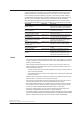
4.1 Error Display on the 7-Segment LED and Corrective Actions Communication Errors The left and right digits of the 7-segment LED display “C” and an error code, respectively. The LED blinks. Display Corrective Action Ref. section C0 Possible Problem DHCP address acquisition error Check network connections. Use a Fixed IP address Check with your network administrator whether your environment supports acquisition of addresses by DHCP. 2.6, 3.
4.1 Error Display on the 7-Segment LED and Corrective Actions Display Possible Problem Corrective Action E040 Invalid client type. Enter a correct client type. E041 Invalid server type. Enter a correct server type. E050 Invalid input type. Enter an input type that can be selected for the module specified by the channel number. E051 Enter an input type that can be selected for all modules specified by the channel range.
4.1 Error Display on the 7-Segment LED and Corrective Actions Display Possible Problem Corrective Action E112 Invalid relay number for relay event. Set the channel number for the DO module. E113 Invalid action type. Enter a correct action type. E114 Invalid combination of edge and level detection actions. Set the edge and level detection types to something different. E115 Invalid combination of level detection actions.
4.1 Error Display on the 7-Segment LED and Corrective Actions 1 Execution Errors The code is divided into two parts which are displayed alternately on the 7-segment LED; in the first part, the letter E appears in the left digit with the hundreds digit of the error code to the right, and the second part consists of the last two digits of the error code. Display Possible Problem Corrective Action E201 Cannot execute due to different operation mode. Confirm the operation mode.
4.1 Error Display on the 7-Segment LED and Corrective Actions Execution Errors The code is divided into two parts which are displayed alternately on the 7-segment LED; in the first part, the letter E appears in the left digit with the hundreds digit of the error code to the right, and the second part consists of the last two digits of the error code. Display Possible Problem Corrective Action E301 CF card error detected. Do not eject or otherwise disturb the card while being accessed.
4.1 Error Display on the 7-Segment LED and Corrective Actions 1 Communication Errors The code is divided into two parts which are displayed alternately on the 7-segment LED; in the first part, the letter E appears in the left digit with the hundreds digit of the error code to the right, and the second part consists of the last two digits of the error code. Display Possible Problem Corrective Action E501 Login first. First, finish logging in. E502 Login failed, try again.
4.2 Error Display in the Monitor Screen and Corrective Actions Error Message Corrective Action Could not connect to the instrument. Check cables and other connections. Check Ethernet cable connections and the IP addresses of devices. Communication error occurred. Check cables and other connections. Check Ethernet cable connections and the IP addresses of devices. The actually installed modules differ from the modules recognized by the system. Reconstruct the module configuration.
4.3 Troubleshooting 1 If servicing is necessary, or if the instrument is not operating correctly after performing the corrective actions below, contact your nearest YOKOGAWA dealer. 2 The 7-segment LED does not illuminate. Possible Problem Corrective Action Ref. section The power switch is not ON. Turn ON the power switch. 2.5 The supply voltage is too low. Check whether the voltage is within the supply voltage rating range. 2.5 The fuse is blown. Servicing required.
4.3 Troubleshooting The MW100 can be detected using the Search button, but browser connection fails. Possible Problem The IP address is set to the default value. The default value cannot be used to make the connection. There is a problem in the network configuration. Corrective Action Set the correct IP address. Check that the IP address, subnet mask, and default gateway settings of the PC and the MW100 settings are correct.
4.3 Troubleshooting The measured value is not correct Possible Problem Corrective Action Ref. section The input wiring is not correct. Check the input wiring. 2.4 The measured value is at +Over or –Over. The measurement range setting and input range do not match. Change to an appropriate setting. 3.5 The temperature error is large or is unstable. The TC type setting and the type actually connected are different. Change to the correct setting. 3.
4.4 Calibration To maintain measuring accuracy, we recommend calibration once per year. Calibration of the instrument requires a calibration instrument of the necessary accuracy and resolution. Please consult with the dealer from whom you purchased the instrument.
4.4 Calibration 1 • When calibrating the RTD range of the 4-CH, High-Speed Universal Input module When calibrating 0 Ω 100Vpk MAX TO 250V MAX CH TO CH 600V MAX TO When calibrating a range other than 0 Ω 2 100Vpk MAX TO 250V MAX CH TO CH 600V MAX TO * Carry out calibration for each input terminal. Input terminal A B Make the resistance of three lead wires equal.
4.
4.4 Calibration • When calibrating the RTD or resistance range of the 6-CH, Medium-Speed Four-Wire RTD Resistance Input module 1 2 I A B C 3 Short the input terminal of CH3 (connect 0 Ω) I A B C Resistance standard 4 * When calibrating the RTD (1 mA) 60 mV range, connect 60 Ω to the input terminal of CH5. When calibrating the RTD (1 mA) 200 mV range, connect 200 Ω to the input terminal of CH6. When calibrating the RTD (1 mA) 600 mV range, connect 300 Ω to the input terminal of CH4.
4.4 Calibration Bridge head (701955 or 701956) For -NDI 1 2 3 4 5 6 7 8 R2 R1 R4 R3 Connect CH2 only Setting switch ON OFF SW 1 2 3 4 5 SW1 SW2 SW3 SW4 SW5 OFF OFF OFF ON OFF • When calibrating the output range of the 8-CH, Medium-Speed Analog Output module All eight channels are calibrated at Zero (0 V) and Full (10 V).
4.4 Calibration Reference Junction Compensation of Thermocouple Input Wiring Diagram Thermocouple wires or 4-CH, High-Speed Universal Copper wires TC extension wires Input Module* Input terminal + – Copper wires DC voltage standard Thermocouple wires Cold junction 0°C standard temperature device * Connect the 10-CH, Medium Speed Universal Input Module and the 30-CH, Medium Speed DCV/TC/DI Input Module in the same manner as well.
4.5 Parts and Maintenance This instrument does not have parts that need periodic replacement. However the main module (model: MW100) has wearable parts listed below. Also, the aluminum electrolytic capacitors below are included with each input/output module. There is no replacement service for the parts listed. If you are to use the MW100 for an extended time, repair or replace the main module according to the service life of the parts and taking into consideration the actual usage conditions.
4.6 System Initialization 1 Perform this procedure to initialize the settings on the MW100. The following types of initialization are available. Initialization Type Type Level 3 Items Initialized Initialization using dip switches ---- All settings Initialization using All communication commands Setting other than configurated module information Initialization Procedure 1. Turn OFF the power to the MW100. 2. Check that the switch 5 of dip switch 1 on the main module is OFF.
4.7 Updating the System You can upgrade the MW100 main unit firmware to the latest version. When you upgrade the version, you can use the upgraded firmware on the MW100. Note that to add new functions by upgrading the style, you need to purchase the style upgrade kit. CAUTION • If you update the firmware, all settings such as the IP address and range settings are reset to factory default values.
4.7 Updating the System 4. Turn ON the MW100. The MW100 starts loading the firmware. If the 7-segment LED displays “90,” the loading operation is complete. If the LED does not display “90,” redo the procedure from “Firmware and Web Software Preparation.” 5. Turn OFF the MW100. 1 2 6. Turn ON switch 4 of the MW100 dip switch 1. To proceed with the updating of the Web software, skip step 7, and carry out the procedure from step 2 in “Updating the Web Software.” 3 7. Turn ON the MW100.
Chapter 5 5.1 Specification Common Specifications 1 Normal Operating Conditions Transport and Storage Conditions Mechanical Specifications (Excluding AC Adapter) Approx. 455 × 131 × 159 mm (when six slots are attached) Approx. 4.3 kg (maximum total weight) Desktop or floor, panel mount, or attached to a DIN rail Steel plate, aluminum die-cast, molded plastic resin Standards Compliance CSA: CSA22.
5.2 Main Module (MW100-E) Specifications Measurement Style number: S3 Measurement range and accuracy: See the measurement range and accuracy given in the specifications of each input module. Maximum number of inputs: 60 inputs (however, only up to six modules can be controlled) Measurement interval: Select from 10, 50, 100, 200, 500 ms, 1, 2, 5, 10, 20, 30, or 60 s.
5.2 Main Module (MW100-E) Specifications Measurement groups: Measurement channels can be divided into up to 3 groups by module. The measurement interval must be the same for all channels in the group. Note that the equivalent of three modules worth of measurement group settings are entered for the 30-CH Medium Speed DCV/ TC/DI Input Module. You cannot assign to different measurement groups or change the measurement interval. You must assign all three slots to the same measurement group.
5.2 Main Module (MW100-E) Specifications Calculations: Basic math (+, –, ×, ÷, exponentiation) Relational operators (>, ≥, =, ≤, <, ≠) Logical operators (AND, OR, XOR, NOT) Arithmetic operators (SQR, ABS, LOG, EXP) TLOG computations (max, min, max-min, average, integration, pulse integration) CLOG computations (max, min, max-min, average) Conditional expressions ([EXPR1?EXPR2:EXPR3]) Order of precedence in expressions: The order of precedence of operators is given below.
5.2 Main Module (MW100-E) Specifications Reference channel: IM MW100-01E 5-5 1 2 3 4 5 Specification Measurement channel MATH channels* Communication input channels Flag input channels MATH constant Program channels * If an expression refers to its own channel or a channel of a larger number than its own channel, the data from the previous MATH interval is used. Communication input channels: 300 Numerical values in expressions can be substituted using communication input.
5.2 Main Module (MW100-E) Specifications MATH alarm function: Four levels per channel Type: Upper limit, lower limit, delay upper limit, and delay lower limit. No hysteresis function available. Loss of computed data: In the monitor screen, when the MATH performance meter exceeds 100%, some computations at each MATH interval cannot be completed, and loss of computed data occurs. When this happens, the previous computed value is held.
5.
5.2 Main Module (MW100-E) Specifications Report Function Specifications (/M3 Option) Report operations: Starts/stops creation of report data at the same time that measurement starts/stops. If recording is in progress at the report creation time, report data is saved to the CF card. Report creation can be turned ON/OFF Report types: Hourly, daily, weekly, or monthly Report data channels: 60 max Measurement and MATH channels can be selected.
5.2 Main Module (MW100-E) Specifications 1 Recorder Structure Measured data, computed data, thinned data, manual sample data, report data, setting values, recording logs, and alarm summaries can be saved to the CF card. Folder Structure IM MW100-01E 5-9 3 4 5 Specification Folders for each file type are created on the CF card, and files are saved in them.
5.2 Main Module (MW100-E) Specifications Capacity of the CF card Capacity needed for storage: The recording starts only if sufficient free space for saving the data is available on the CF card. The required free space is a total of the following sizes. • Space for storing the measured, computed, and thinned data.
5.2 Main Module (MW100-E) Specifications Pretrigger function: Trigger Type Direct Trigger IM MW100-01E Selectable data length 30 min. 1, 2, 3, 4, 6, 8, or 12 hours 1, 2, 3, 5, 7, 10, 14, or 31 days 10, 20, or 30 min. 1, 2, 3, 4, 6, 8, or 12 hours 1, 2, 3, 5, 7, or 10 days Target All groups Individual groups 5-11 1 2 3 4 5 Specification The pretrigger when the recording start action is set to Trigger can be set for each interval group from 0 to 100% in 10% intervals.
5.2 Main Module (MW100-E) Specifications File size: Within approximately 10 Mbyte per file *1 *2 File size calculation: File size (bytes) = header size + data size *1 Header size (bytes) = Fixed length of 1448 + no. of recording channels × 232 *2 Measurement data size (bytes) = no. of recording measurement channels × 4 × no. of samples Math data size (bytes) = no. of recording math channels × 6 × no. of samples No. of samples = Data length (s)/recording interval (s) Ex.) Recording interval: 100 ms; no.
5.2 Main Module (MW100-E) Specifications Thinning Recording Function IM MW100-01E 5-13 1 2 3 4 5 Specification Apart from the measured and computed data file, a set of thinned data from the measured and computed values are saved to CF card. Record start/stop: Executed simultaneously with the start/stop of the recording of measured and computed values. No trigger functions are available.
5.2 Main Module (MW100-E) Specifications Manual Sample Recording Function Manual sample operation: • When Manual Sample is executed using an Event/Action, communication command, or status screen operation, the latest measured or computed values are saved to the CF card. If a manual sample operation is executed while writing to a manual sample file is in progress, the operation is ignored. Also, the manual sample file is divided when Manual Divide is executed.
5.2 Main Module (MW100-E) Specifications Report Recording Function (/M3 Option) Saving Settings Saves settings to CF card. Saving/loading: Set by user function key on the main unit, browser, or by communication command. From the user function key, only the SETTING.PNL file can be saved and loaded.
5.2 Main Module (MW100-E) Specifications Internal Backup Memory Function overview: Using the main unit’s internal backup memory (SRAM) even upon a power failure, data before the failure is saved to CF card without loss. Backup memory capacity: For measured and computed data 1.
5.2 Main Module (MW100-E) Specifications 1 Communication Ethernet Port Interface: Ethernet 10BASE-T/100BASE-TX The data rate can be fixed to 10 Mbps half duplex by turning switch 6 of dip switch 1 OFF. Connector type: RJ-45 Main protocols: FTP, SMTP, SNTP, DHCP, DNS, HTTP, Modbus/TCP, and MW100 dedicated protocol. Communication services: Send/receive measured and computed values, send/receive setting values, maintenance/diagnostic services, and others.
5.2 Main Module (MW100-E) Specifications SNTP function: Client function: Acquires time information from the specified SNTP server when the power is turned on, upon start of measurement, when the SNTP client is turned ON, at a user-specified time, and at a specified time interval. When time information is acquired upon startup, measurement start, and when the SNTP client is turned ON, the time is not applied if the difference between the time of the MW100 and the server is 1 hour or more.
5.2 Main Module (MW100-E) Specifications HTTP function: Enables entry of settings on the MW100, starting and stopping of measurement, computation, and recording, and real time monitoring of measured and computed values using a Web browser, as well as acquisition of CF card files using WebDAV.
5.2 Main Module (MW100-E) Specifications Communication Output Function The following information about the main unit can be output using communication commands. For information about communication commands, see the MW100 Communication Command Manual (IM MW100-17E).
5.
5.2 Main Module (MW100-E) Specifications Command settings: Up to 100 commands can be set. Command items: Loading channels: C001 toC300 Writing channels: 001 to 060, A001 to A300, C001 to C300 Address: 1 to 247 Input registers: 30001 to 39999, 300001 to 365535 Hold registers: 40001 to 49999, 400001 to 465535 Type: Type Description Int 16 Signed 16-bit integer Uint 16 Unsigned 16-bit integer Int 32 - Big Signed 32-bit integer (from upper to lower.
5.2 Main Module (MW100-E) Specifications 1 Register Assign (Modbus Server Functions and Sharing) * Coil 00001 00002 | 00300 Data Data type Data on communication input channel C001 Bit Data on communication input channel C002 Bit | | Data on communication input channel C300 Bit Communication input channel coils are 0 (Off) when data is zero, infinite (+Inf, –Inf), or NaN, and 1 (On) when data is one or non-infinite. * Firmware version R3.
5.2 Main Module (MW100-E) Specifications Input Registers Data 33001 Lower byte of computed data of computation channel A001 33002h Upper byte of computed data of computation channel A001 | | 33599 Lower byte of computed data of computation channel A300 33600 Upper byte of computed data of computation channel A300 .
5.2 Main Module (MW100-E) Specifications Values per Modbus Registers (Measurement channel data and MATH channel data) The main module handles data on measurement channels as type Int16, and data on MATH channels as type Int32. The Modbus register values of these data are shown in the table below. Value type Name/description of value Note This is an example of acquiring decimal place information.
5.2 Main Module (MW100-E) Specifications Values per Modbus Registers (Communication input channel data) The main module handles data from the communication input channels as type Float. The Modbus register values of these data are shown in the table below. Comm. Input Channel Data (Float)(x) Value (y) per Modbus Register *1 Float Int 32 Int 16 Bit min = –2,147,483,648 min = –32,768 max = 2,147,483,647 max = 32,767 +Inf +Inf max max 0 –Inf –Inf min min 0 NaN NaN max max 0 *2 *2 *3 Valid Data (physical qty.
5.2 Main Module (MW100-E) Specifications Modbus Client Function (/M1 option) Modbus Server Function Communication possible with Modbus/TCP protocol Communication media: Ethernet 10BASE-T/100BASE-TX Port: 502/tcp Maximum no. of simultaneous connections: 4 Receive timeout: Drops communication connection if packets not received for 30 s (fixed) or more Supported function: Same as Modbus slave function. However, there is no function code 8 (loopback test).
5.2 Main Module (MW100-E) Specifications EtherNet/IP Server Function (Firmware version R3.02 or later) The server function enables you to read measured data from MW100 measurement channels, and computed data from MW100 math channels, and read/write data on communication input channels. Specifications Implementation Connection Protocol Messaging Object 5-28 Descriotion Level 2 (Message Server + I/O Server) Max.
5.2 Main Module (MW100-E) Specifications 1 Event Action Timer and Match Time Internal Timer No. of timers: Types of timers: Relative time timer: Absolute time timer: 6 Two; Relative timer and Absolute timer Repeats time up every specified time interval. Time interval can be set in 1-minute intervals. Setting range is 00 days 00 hours 01 min. to 31 days 23 hours 59 minutes. If the setting of the relative timer is changed or in the event of a power failure, the timer is reset to 0 and starts again.
5.
5.2 Main Module (MW100-E) Specifications Log Information Item Maximum no. saved Operation log 256 Error log 50 Message summary 50 Communication log 200 FTP client log 50 SNTP client log 50 SNTP client log 50 DHCP client log 50 FTP server log 50 HTTP server log 50 Modbus master log 50 Modbus client log 50 Modbus slave log 50 Modbus server log 50 Computation status 1 Recording status 1 Maximum no.
5.2 Main Module (MW100-E) Specifications Initializing Settings Two types of settings initialization are available. Initialization of all settings: Initializes all setting values and measured values on the main unit. You can perform initialization through communication commands, from the browser, or by resetting the dip switch positions and turning ON the unit. However, when initialized using communication commands or the browser, module recognition information is not initialized.
5.
5.3 Base Plate (MX150) Specifications Number of main modules that can be attached: 1 (always attached) Number of input/output modules that can be attached: 1 to 6* (specified by the suffix code) * One 30-CH Medium Speed DCV/TC/DI Input Module uses three modules worth. External dimensions: Approx. 118 to 408 (W) × 75 (H) × 35 (D) mm Weight: Approx. 0.37 kg (1 main module, for connecting six input/output modules) External Dimensions Units: mm MX150-1, -2, -3, -4, -5, -6 407.
5.
5.4 4-CH, High-Speed Universal Input Module (MX110-UNV-H04) Specifications Measurement Accuracy Measurement Highest Rated Measurement Accuracy Integration Time: 16.67 ms Range Resolution Measurement Integration Time: 1.67 ms or More Type (1 digit) Range Pt100*1 –200.0 to 600.0°C 0.1°C ±(0.1% of rdg + 1.5°C) ±(0.05% of rdg + 0.3°C) JPt100*1 –200.0 to 550.0°C Pt100 (high res.) –140.00 to 150.00°C ±(0.05% of rdg + 0.3°C) 0.01°C ±(0.1% of rdg + 1.5°C) RTD JPt100 (high res.) –140.00 to 150.
5.4 4-CH, High-Speed Universal Input Module (MX110-UNV-H04) Specifications IM MW100-01E 5-37 1 2 3 4 5 Specification Reference junction compensation accuracy: When measuring temperature greater than or equal to 0°C and when the temperature of the input terminal is balanced Type R, S, W: ±1°C Type K, J, E, T, N, L, U, XK GOST: ±0.
5.4 4-CH, High-Speed Universal Input Module (MX110-UNV-H04) Specifications Effects of Operating Conditions The specifications below apply when the integration time is 16.67 ms or more. Warm-up time: At least 30 minutes after power-up Effects of ambient temperature: The effect received by changes in 10°C increments of the ambient temperature is ±(0.05% of rdg. + 0.05% of range) or less However, for Cu10 Ω: ±(0.
5.
5.5 10-CH, Medium-Speed Universal Input Module (MX110-UNV-M10) Specifications Input Measurement Range Type Pt100*1 JPt100*1 Pt100 (high res.) JPt100 (high res.) Ni100 SAMA*2 Ni100 DIN*2 Ni120*3 Pt50 Cu10 GE*4 Cu10 L&N*4 Cu10 WEED*4 Cu10 BAILEY*4 J263B Cu10 at 20°C alpha=0.00392 Cu10 at 20°C RTD (Measurement alpha=0.00393 current: 1 mA) Cu25 at 0°C alpha=0.00425 Cu53 at 0°C alpha=0.00426035 Cu100 at 0°C alpha=0.
5.5 10-CH, Medium-Speed Universal Input Module (MX110-UNV-M10) Specifications IM MW100-01E 5-41 1 2 3 4 5 Specification Reference junction compensation accuracy: When measuring temperature greater than or equal to 0°C and when the temperature of the input terminal is balanced Type R, S, W: ±1°C Type K, J, E, T, N, L, U, XK GOST: ±0.
5.5 10-CH, Medium-Speed Universal Input Module (MX110-UNV-M10) Specifications Effects of Operating Conditions The specifications below apply when the integration time is 16.67 ms or more. Warm-up time: At least 30 minutes after power-up Effects of ambient temperature: The effect received by changes in 10°C increments of the ambient temperature is ±(0.05% of rdg. + 0.05% of range) or less However, for Cu10 Ω: ±(0.
5.
5.6 30-CH, Medium-Speed DCV/TC/DI Input Module (MX110-VTD-L30) Specifications Measurement Interval, Integration Time, and Filter: Measurement Integration Interval Time 500 ms 1s 1.67 ms 16.67 ms 20 ms Auto*2 Burnout Detection Cycle Filter Rejected Noise and Notes 600 Hz and its integer multiples*1 60 Hz and its integer multiples Rectangular 50 Hz and its integer multiples Automatically detects the power supply frequency and set Measurement 16.
5.6 30-CH, Medium-Speed DCV/TC/DI Input Module (MX110-VTD-L30) Specifications Up/Down setting is possible 2 kΩ or less normal, 200 kΩ or more disconnected (shunt capacitance: 0.01 μF or less), detection current approx. 10 μA, detection time approx. 1.6 ms Power consumption: Approx. 1.2 W External dimensions: Approx. 174 (W) × 131 (H) × 150 (D) mm (including the terminal cover) Weight: Approx. 0.8 kg. Terminal type: Clamp, or M3 screw terminal (if /H3 option is added) 2 Applicable wire size: 0.14 to 1.
5.
5.7 6-CH, Medium-Speed Four-Wire RTD Resistance Input Module (MX110-V4R-M06) Specifications Input Measurement Range Type Pt500*2 Measurement Accuracy Integration Time: 16.67 ms or More Rated Measurement Range –200.0 to 600.0°C Measurement Accuracy Integration Time: 1.67 ms RTD*3 (Measurement ±(0.1% of rdg + 1.5digits) ±(0.05% of rdg + 3digits) current: 0.25 Pt1000*2 –200.0 to 600.0°C mA) 20 Ω ±(0.05% of rdg + 7digits) ±(0.1% of rdg + 25digits) 0.000 to 20.00 Ω (Measurement current 1 mA) 200 Ω ±(0.
5.7 6-CH, Medium-Speed Four-Wire RTD Resistance Input Module (MX110-V4R-M06) Specifications Noise rejection: Rejection by the integrating A/D converter and the use of low pass filters Input resistance: For DC voltage 1 V range or less: 10 MΩ or less For DC voltage 2 V range or higher: Approx.
5.7 6-CH, Medium-Speed Four-Wire RTD Resistance Input Module (MX110-V4R-M06) Specifications 1 General Specifications Operating temperature range: Operating humidity range: –20 to 60°C 20 to 80% RH for –20 to 40°C 10 to 50% RH for 40 to 50°C 5 to 30% RH for 50 to 60°C 2 External Dimensions Units: mm 57 3 150.8 4 5 131 Specification App If not specified, the tolerance is ±3%. However, in cases of less than 10 mm, the tolerance is ±0.3 mm.
5.
5.8 4-CH, Medium-Speed Strain Input Module (MX112) Specifications * Does not apply to the NDIS terminal. Effects of Operating Conditions The specifications below apply when the integration time is 16.67 ms or more. Warm-up time: At least 30 minutes after power-up Effects of ambient temperature: The effect received by changes in 10°C increments of the ambient temperature is ±(0.
5.8 4-CH, Medium-Speed Strain Input Module (MX112) Specifications General Specifications Operating temperature range: Operating humidity range: –20 to 60°C 20 to 80% RH for –20 to 40 °C 10 to 50% RH for 40 to 50 °C 5 to 30% RH for 50 to 60 °C External Dimensions Units: mm -B12, -B35 -NDI 57 57 4.8 133.8 131 131 150.8 If not specified, the tolerance is ±3%. However, in cases of less than 10 mm, the tolerance is ±0.3 mm.
5.9 10-CH, Pulse Input Module (MX114) Specifications 1 Style number: Number of Inputs: Input type: S3 10 Pull up internally at approx. 5 V/approx. 5 kΩ, non-isolated between channels Measurement interval: Select 100 ms, 200 ms, 500 ms, 1 s, 2 s, 5 s, 10 s, 20 s, 30 s, or 60 s.
5.9 10-CH, Pulse Input Module (MX114-PLS-M10) Specifications Contact/transistor rating: Contact with a rating of 15 VDC or more, and 30 mA or more Transistor with a rating of Vce > 15, and Ic > 30 mA Maximum input voltage: ± 10 V Insulating resistance: Input terminals to ground: 20 MΩ or more (500 VDC) Withstand voltage: Input terminal to ground: 2300 VAC (50/60 Hz), for one minute Maximum common mode voltage: 250 VACrms (50/60 Hz) Terminal type: Clamp Power consumption: Approx. 1.
5.10 10-CH, High-Speed Digital Input Module (MX115) Specifications 1 General Specifications Operating temperature range: Operating humidity range: –20 to 60°C 20 to 80% RH for –20 to 40°C 10 to 50% RH for 40 to 50°C 5 to 30% RH for 50 to 60°C External Dimensions Units: mm 57 131 150.8 If not specified, the tolerance is ±3%. However, in cases of less than 10 mm, the tolerance is ±0.3 mm.
5.
5.11 8-CH, Medium-Speed Analog Output Module (MX120-VAO-M08) Specifications 1 External Dimensions Units: mm 57 150.8 2 3 131 4 5 If not specified, the tolerance is ±3%. However, in cases of less than 10 mm, the tolerance is ±0.3 mm.
5.12 8-CH, Medium-Speed PWM Output Module (MX120-PWM-M08) Specifications Style number: Number of outputs: Update interval: Output interval: S2 8 100 ms minimum (not synchronized to the measurement interval) 1 ms to 300 s (can be set channel by channel) However, 1 ms interval setting range: 1 ms to 30.000 s (can be set in units of 1 ms) 10 ms interval setting range: 10 ms to 300.
5.12 8-CH, Medium-Speed PWM Output Module (MX120-PWM-M08) Specifications 1 General Specifications Operating temperature range: Operating humidity range: –20 to 50°C 20 to 80% RH for –20 to 40 °C 10 to 50% RH for 40 to 50°C 2 External Dimensions Units: mm 57 150.8 3 4 131 5 Specification App If not specified, the tolerance is ±3%. However, in cases of less than 10 mm, the tolerance is ±0.3 mm.
5.13 Operations Common to the 8-CH MediumSpeed Analog Output Module and the 8-CH Medium Speed PWM Output Module (MX120) Settings Related Specifications (by Module) Setting channel Setting Contents (Module) Output Channel Span Setting AO(V) (AO, PWM) range AO(mA) PWM –10.000 to 10.000V Settings Remarks — — The output range for arbitrary output is within the range on the left — Yes — No — 0.000 to -20.000 mA 0.000 to 100.000% Preset value Setting range AO(V) –11.000 to 11.000V AO(mA) 0.
5.14 10-CH, Medium-Speed Digital Output Module (MX125) Specifications 1 Style number: Number of outputs: Contact mode: Update interval: Contact capacity: Contact life*: General Specifications Operating temperature range: Operating humidity range: –20 to 50°C 20 to 80% RH for –20 to 40°C 10 to 50% RH for 40 to 50°C External Dimensions Units: mm 57 131 150.8 If not specified, the tolerance is ±3%. However, in cases of less than 10 mm, the tolerance is ±0.3 mm.
Appendix Appendix 1 Supported Characters 1 When entering characters on the MW100 from a browser, the following characters can be used. There are limits to which characters can be used depending on the type of entry item. For information on the characters can that can be used in communication commands, see the MW100 Communication Command Manual (IM MW100-17E).
Appendix 2 Setting Data Communication That Uses Modbus Protocol This section descries the procedure for data transmission and reception based on a configuration in which two MW100s are connected for Modbus communications (Modbus/ TCP) over an Ethernet. Note that the MATH function (/M1 option) is required to use the Modbus client function. Setup Procedure The following shows the procedures for entering settings, from connecting to the Ethernet to applying the data acquired via Modbus communications.
Appendix 2 Setting Data Communication That Uses Modbus Protocol 1 Setup Example Data is sent and received between the MW100 client and MW100 server. The MW100 client loads and displays measured data from measurement channels 001 to 004 of the MW100 server, and also writes that data to the MW100 server. The following is an example in which the data written to the MW100 server is displayed. Measured data READ request Com. input ch.
Appendix 2 Setting Data Communication That Uses Modbus Protocol 2. Computed data from MATH channels A001 to A004 of the MW100 client are written to communication input channels C001 to C004 of the MW100 server.
Appendix 2 Setting Data Communication That Uses Modbus Protocol 1 Client Setting 2 Enter settings for the destination server. Enter the IP address of the server Enter the IP address or host name of the destination server. In the example, an IP address of “192.168.1.101” is entered. Enter the server port number Enter the port number of the destination server. In the example, “502” is entered. 2 3 4 Client Setting 3 Enter settings for registers to be used for receiving data.
Appendix 2 Setting Data Communication That Uses Modbus Protocol Client/Server Settings for WRITE The screens in the explanations below were generated under firmware version R3.04. Server-Side Settings Server Settings Set the MW100 server as the server device. These are the same as the server-side settings for READ. MATH Channel Settings In order to display data written to the hold registers from the MW100 client, enter the communication input channel numbers in the MATH channel expression entry area.
Appendix 2 Setting Data Communication That Uses Modbus Protocol 1 Starting Communication Starting Measurement and Computation MATH channels must be displayed to show transmitted data. After starting measurement, start computation. 2 Displaying Data When data is sent/received via Modbus communication, the following waveform is displayed on the monitor screen of a Web browser.
Appendix 2 Setting Data Communication That Uses Modbus Protocol Checking the Communication Status You can view log information to check the status of Modbus communications. Modbus communication log information You can check the status of communication and other information by selecting items here. For information about displayed contents, see the MW100 Communication Command Manual (IM MW100-17E).
Appendix 3 Using the Event Action 1 This section introduces an example in which the event action function is used to save the data. • Saving data on the hour • Acquiring periodic data (periodic report) • Diving the data on each event 2 3 Saving Data on the Hour Data is saved on the hour by setting the event to Timer and action to Memory Save. In this example, data is saved at hour 0 using Memory Save.
Appendix 3 Using the Event Action Diving the Data on Each Event Data is divided by setting the input/output event and the action to Memory Save. • Setting the event action Event: DI, Alarm, Relay, UserKey, etc.
Appendix 4 E-Mail Format 1 In the explanations that follow, CRLF means “carriage return/line feed.” A user-defined character string can be attached to the subject of each mail.
Appendix 4 E-Mail Format uuuuuu Unit information (output using 6 chars., left justified) mV____: mV V_____: V ^C____: °C XXXXXX: (user specified char. string) _ Blank Note If measured / computed data results in an error (+Over, –Over, Invalid, or Illegal), the errors are sent without the values.
Appendix 4 E-Mail Format rrrrrrrrr Report data (excluding integral value, sends in the order maximum/ minimum/average/instantaneous value, includes decimal point and minus sign, all space filled in to the left when 8 characters or fewer) eeeeeeeeeeeee Integral data (includes exponent display (e.g.: -4.000000E+19), decimal point, minus sign, and E, all space filled in to the left when 12 characters or fewer) uuuuuu Unit information (output using 6 chars.
Appendix 4 E-Mail Format Media Remaining Space Notification E-mail Format • Subject Subject: [Media Remain] • Syntax CRLF Media_RemainCRLF
Appendix 4 E-Mail Format 1 System Error Notification E-mail Format • Subject Subject: [ERROR] 2 • Syntax CRLF ERRORCRLF
Appendix 4 E-Mail Format mmmm Computation channel no. (A001 to A300, OFF channels not output) f Minus sign (omitted if +) ddddddd Measured data (measurement channel, includes decimal point and minus sign, all space filled in to the left when 6 characters or fewer) eeeeeeeee C omputed data (MATH channel, includes decimal point and minus sign, all space filled in to the left when 8 characters or fewer) uuuuuu Unit information (output using 6 chars.
Appendix 5 Retrieving Files Using WebDAV 1 The MW100 communication service contains the WebDAV function. This function is used to operate the files on the CF card that is attached to the MW100 or retrieve the files. This section explains the method using a browser. Internet Explorer is used for the browser. Another method is to use Create a new connection from My Network Places. 2 You can perform file operations such as move and copy in the same manner as normal files.
Appendix 5 Retrieving Files Using WebDAV For Windows Vista 1. To use the WebDAV function, you must apply the patch provided by Microsoft. Download the file from their Web site and apply (install) the patch. There is a link to the Microsoft Web site on the Yokogawa MW100 Web site. 2. Right click the Start menu and select Explorer. The Windows Explorer opens. 3. In the Explorer, right-click Computer and select Map Network Drive... The Map Network Drive window is displayed. 4.
Appendix 5 Retrieving Files Using WebDAV 1 5. Click the Next button. The Connect to the Internet and Add Network Location windows appear. 2 3 4 5 6. Click the Cancel button in the Connect to the Internet window to close it. 7. Select the Add Network Location window. Click Select Choose a custom network location, then click the Next button. App Appendix Index 8. Enter the IP address of the MW100 in the Internet or network address box, then click the Next button.
Appendix 5 Retrieving Files Using WebDAV 9. Enter the WebDAV name in the “Type a name for this network location” box, then click the Next button. Use an easy-to-identify name. 10. Click the Finish button. Settings complete. If you open the Explorer and select a Web folder, the folder opens.
Appendix 6 Network Terminology 1 Network Terminology Term 2 Description IP address An ID that is assigned to each PC or communication device on an IP network such as the internet or an intranet. The address is a 32-bit value expressed using four octets in decimal notation (each 0 to 255), each separated by a period as in 211.9.36.148. Subnet mask TCP/IP networks such as the Internet are often divided up into smaller networks called sub networks.
Appendix 7 Using the Broken Line Data of Decimal Values Because the output value of a program channel is an integer, an expression is used to output decimal values. • Setting Example A001=P01/K01 Here, MATH channel is A001, program channel is P01, and calculation constant is K01. A001 Y: Output value (30, 2.2) (40, 2.2) (10, 1.5) (20, 1.5) (0, 0.0) (50, 0.0) X: Time (s) • Entry Example Set the calculation constant as K01=10. The broken line data P01 is as follows: (0.0), (10.15), (20.15), (30.
next T = create 06/09/15 18:00:00 Write time of thinning recording Write operation type none: No write operation create: File creation write: Data writing Indicates the write times of the interval group or thinning recording The number following next indicates the group number (1 to 3) or thinning (T) Appendix 8 Saving Data to the CF Card 1 2 Write Timing Write Timing You can check the time when data is written to the CF card using the recording status in the log information.
Appendix 8 Saving Data to the CF Card The data save operations is as follows: Length of one data writing Start Data length Data writing time Time (s) 1 2 3 4 5 6 7 8 Next file 8th data writing File complete 1st data writing File generation start Replacing the CF Card While Recording You can replace the CF card while recording is in progress. Replace the CF card while the access indication to the CF card is not showing. An access forewarning is indicated before the CF card is accessed.
Appendix 8 Saving Data to the CF Card 1 Write Count When data is saved to the CF card, the data is written several times in sections. The write count can be calculated in advance. 2 Equation The relationship between the data length and write count is as follows: Data length = write length × write count Because the write length is designed not to exceed the storage time (one-half the time that can be stored in the internal memory), write length is less than the storage time.
Index Index 1 Numerics B 10-CH, High-Speed Digital Input Module................... 1-51, 5-55 10-CH, Medium-Speed Digital Output Module........... 1-59, 5-61 10-CH, Medium-Speed Universal Input Module......... 1-38, 5-39 10-CH, Pulse Input Module........................................ 1-49, 5-53 10 Mbps half duplex............................................................ 2-24 1 gauge 3 wire method........................................................ 2-14 1 gauge method...........................
Index D daily..................................................................................... 1-72 data length.................................................................. 5-11, 5-19 data save folder..................................................................... 5-9 data save folder settings..................................................... 3-23 data transfer settings............................................................. 3-8 data view...............................................
Index I in-progress display.............................................................. 1-13 initial balancing........................................................... 1-46, 3-28 initialization of the CF card.................................................. 5-32 initialization procedure......................................................... 4-19 initialization type.................................................................. 4-19 initializing settings............................................
Index MX114................................................................................. 5-53 MX115................................................................................. 5-55 MX120-PWM-M08...................................................... 5-58, 5-60 MX120-VAO-M08....................................................... 5-56, 5-60 MX125................................................................................. 5-61 MX150..................................................................
Index S IM MW100-01E 1 2 3 4 T tag name display................................................................. 3-69 tag name settings................................................................ 3-65 tag strings................................................................... 1-18, 5-30 temperature unit.................................................................. 3-16 terminal arrangement markings............................................. 2-6 terminal block................................
Index U uint16................................................................................... 5-22 uint32-big............................................................................. 5-22 unbalance adjustment......................................................... 1-46 unit32-little........................................................................... 5-22 unit number.................................................................. 2-5, 3-16 unit number display...............................