MW100 CAN Bus Module (MX118-CAN-M30/S1) User’s Manual 1/17 All Rights Reserved.
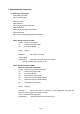
Contents 1. Foreword ................................................................................................................................................ 3 2. System Reconfiguration........................................................................................................................ 3 3. Setup....................................................................................................................................................... 3 3.1.
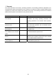
1. Foreword This manual describes the functions, operating procedures, and handling precautions applicable to the CAN Bus Module (MX118-CAN-M30/S1) when installed in the CAN bus module–compatible MW100 Data Acquisition Unit. Items not included in this manual can be found in the following manuals for the standard MW100 Data Acquisition Unit. Read them along with this manual. Manual Name Manual No.
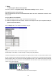
2. System Reconfiguration When connecting the MW100 for the first time, or when changing the position of an installed input/output module on the connected MW100, reconfiguration is performed to match up the system with the actual modules. Before reconfiguration, connect to the MW100 to be reconfigured. Setting Module Information (1). From the top screen, click System Settings > Module information under the Top item. (2).
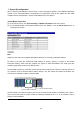
3. Setup 3.1.Setting Up the Measurement Operation From the top screen, click System Settings > Measurement Setting under the Top item. Entering Measurement Group Settings Select a measurement interval from the Measurement Interval list. Set a measurement interval for each group number. Assigning Measurement Modules (1). Select the group you wish to assign in the Measurement groups list. (2). Select an integral time of AUTO, 50 Hz, or 60 Hz in the Integral Time box.
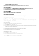
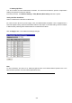
The relationship between the measurement interval and the maximum number of channels that can be set is the same as that in the MW100 standard specifications (in the table below). Measurement Interval 10 ms 10/50 ms mixed Max. Number of Channels Set 10 10 50 ms 30 100 ms– 60 Notes The max. number of channels that can be set refers to the total number of valid input channels excluding channels set to SKIP, and is applied across multiple modules.
3.2.Setting Up Measurement Channels You can set the input type, range, span, computations, difference input, and scale. Setting the Input Range (1). From the top screen, click Channel Settings > AI/DI Channel settings under the Top item. (2). Select the channel group you wish to set from the Channel list box. Setting the Input Mode Select an input mode of COM or SKIP from the Mode list. Setting the Measurement Range Only the measurement range of CAN can be selected from the Range list.
Note Linear scaling (SCALE) and difference input (DELTA) cannot be selected at the same time. If the input type setting does not match that of the MW100, measurements may not be performed correctly. The output data will be “Invalid” (if the setting on the MW100 is COM and the channels set on the module are OFF).
3.3.Setting Up Filters You can set filters for CAN measurement channels. The burnout and reference junction compensation settings are ignored for CAN bus modules. From the top screen, click Channel Settings > Filter,Burnout,RJC setting under the Top item. Setting the Filter Coefficient Select a coefficient from the Filter Coefficient list.
4. Communication Commands 4.1.Setting the Input Range When setting p2=SKIP SR p1,p2 When p2=COM When p6=OFF SR p1,p2,p3,p4,p5,p6 When p6=DELTA SR p1,p2,p3,p4,p5,p6,p7 When p6=SCALE SR p1,p2,p3,p4,p5,p6,p7,p8,p9,p10 When Setting Channels to SKIP Syntax SR p1,p2 p1 Channel range (001–060) p2 Input mode (SKIP) Query SR[p1]? Example) Set channel 1 to SKIP. SR 001,SKIP Explanation) Channels set to SKIP are not measured.
When Setting Difference between Channels Computation Syntax SR p1,p2,p3,p4,p5,p6,p7 p1 Channel range (001–060) p2 Input mode (COM) p3 Measurement range (CAN) p4 Lower limit of span (-30000–30000) p5 Upper limit of span (-30000–30000) p6 Computation mode (DELTA) p7 Reference channel number (001–060) Query SR[ p1]? Example) Set the MATH type for channel 10 to difference computation between channels with channel 1 (the reference channel), set the input type to COM(CAN), the lower limit of span to
5. PC Software Use PC software of the following release numbers or later. Software Software Name Release No. MW100 IP Setting Software MW100 Viewer Address Setting R2.06 MW100 Viewer MW100 Viewer Data Viewer R2.06 MW100 Calibrator MW100 Viewer Calibrator R2.
6. CAN Bus Module (MX118-CAN-M30) Specifications 6.1.Model Name Model Name Description Max. Number of Channels Min. Sampling Interval Slot Width MX118-CAN-M30 CAN Bus Data Acquisition Module 30 ch 10 ms 1–3 6.2.Module Specifications Number of Channels: 30 ch/module No. of messages (ID): 30 Sampling interval: 10 ms–60 s Max. no. of installed modules: Differs by slot width setting (no. of ch used per module) Slot Width Setting 1 2 3 Max. No. of Ch Used 10 ch 20 ch 30 ch Max. no.
For scaling computation When (Value width/Span width) > 1, Value width is changed to within the span width. For such settings, the resolution of values computed with scaling computation is lower than Value Max/Value Min.
Weight: Approximately 0.
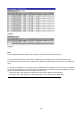
Dip Switch Settings ON 1 2 3 4 5 6 7 Dip Switch No. Setting mode 1 2 3 4 5 6 7 8 Baud rate 57600bps ON OFF OFF OFF OFF OFF OFF - Baud rate 9600bps ON ON OFF OFF OFF OFF OFF - OFF OFF OFF OFF OFF OFF OFF - ON - - - - - - - ON OFF - - - - - - - OFF Measurement mode CAN bus comm. terminator -:Don’t care Note Number of channels is limited to 10 per unit when the sampling interval is 10 ms.
7. Switching between Setting and Measurement Mode When measuring (acquiring) CAN bus data on a CAN bus module, you can insert other I/O modules in the MW100 and perform measurements on them at the same time. However, when the CAN module is installed in the MW100, the CAN settings are entered using dedicated setting software (CAN Bus Module Configuration Tool) via external serial communications. 7.1.