
Instruction Manual

13
IM CA150E
RSLogix 500
®
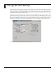
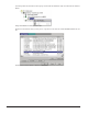
Write Message
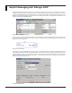
Once the Control Block is designated, the Setup Screen can be confi gured. The fi rst item to fi ll in is the location of the data that
is to be written from the PLC to the MW100, designated as the Data Table Address. In this case N7:49 is chosen with an element
size of 1 (one byte of data - in order to read or write large amounts of data in a single message, increase the elements size to
the appropriate value). Channel 0 designates what port to use on the PLC (in this case the serial port for DF1 communications
– later routed via a DigiOne IAP (DF1 to EIP gateway)).
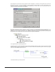
The next step is to confi gure where the message will be written. In this case a Message Timeout of 5 seconds is used and Com-
munication Channel C001 is being written to as an integer using the syntax N30:0 for Data Table Address. In this case Local
Node Addr is set to 1 so that the gateway device knows to route all commands issued to Node 1 to the IP address of a specifi c
MW100. If multiple MW100s are on a network then using different Node Addresses within the message commands can be used
in conjunction with a gateway to route messages to specifi c MW100s (e.g., Node 1 to MW100 A, Node 2 to MW100 B, etc…).
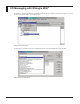
Write Message Setup Screen as confi gured for PLCs that support DF1