User's Manual DAQMaster MW100 Ethernet/IP Instruction Manual DAQMaster MW100 Ethernet/IP Instruction Manual IM MW100EIP 2nd Edition: Apr.
Table of Contents Table of Contents......................................................................................................................................................... 1 Introduction ................................................................................................................................................................. 2 Explicit Messaging ............................................................................................................................
Introduction There is a large install base of industrial automation Programmable Logic Controllers (PLCs) and remote I/O that support Ethernet/IP (EIP) also known as Control and Information Protocol (CIP) over Ethernet. Most notable is the family of PLCs and I/O manufactured by Allen-Bradley® (AB) consisting of: PLC 2®, PLC 5®, SLC 500®, MicroLogix®, CompactLogix® and ControlLogix®.
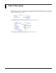
Explicit Messaging Explicit Messaging is a point to point, request/response messaging protocol for unscheduled information transfer. In ladder logic programming explicit messaging is usually denoted by a messaging command that is all inclusive (what is going to be read or written and to what register in what device).
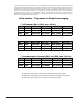
The tables below detail the naming convention to use when creating explicit messages within RSLogix®. In the left most column is the native MW100 register starting with I/O channels 001 through 060, Computation Channels A001 through A300 (also known as Math Channels) and finally Communication Channels C001 through C300. I/O Channels and Computation Channels are considered read only while Communication Channels are read/write.
When using RSLogix 5000® and RSLogix 500® there are different types of messages that correspond to the different type of PLCs. Everything from AB PLC 2® through AB ControlLogix® PLC can be communicated using the MSG block. The following covers all the MSG instructions supported by the MW100 with EIP. Step by step examples of explicit messaging within RSLogix 500® and RSLogix 5000® are detailed in Appendix A.
I/O Messaging (Implicit Messaging) I/O Messaging, also known as Implicit Messaging, is used for point to point or multicast and to transmit application specific I/O data. Implicit messages are exchanged across I/O connections with a Connection ID (predefined path as first defined in RSLinx® and then RSLogix®). The Connection ID will define where the MW100 is located (IP Address), the Ethernet port on the PLC through which to communicate, as well as what points are considered inputs or outputs.
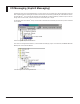
By clicking on ETHERNET-MODULE MW100 within the Controller Organizer tree, the connection can be fully configured. Note - the IP Address should point to an MW100, Comm Format which defines what data types to use and Connection Parameters which layout the inputs and outputs of the MW100. In this case, the connection is configured to communicate using double precision integers to an MW100 at IP address 10.0.232.
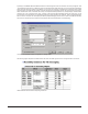
Once an instance has been properly configured, the MW100 inputs and outputs will show up in the Controller Tags window. MW100 Channels within RSLogix 5000® Controller Tags Screen These points can now be assigned as inputs and outputs as well as monitored (when online) within programs as shown in the example below. Note that the tags can be used within any logic element (not just MSG blocks as with Explicit Messaging).
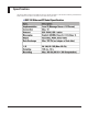
Specification The following table describes how the MW100 conforms to the EIP specification. Note that when interfacing to the MW100 on an EIP network no more than 10 connections can be active at any given time.
Summary The MW100 with EIP support can easily communicate via Explicit or I/O messaging to a variety of PLCs. The MW100 requires the PLC to initiate all communications. Now that the MW100 can communicate with EIP based PLCs, the full capabilities of the DAQMaster MW100 can easily be added to a controller network. A PLC can use the MW100 as remote inputs and outputs within its control logic.
Appendix A – Detailed Explicit and I/O Messaging using RSLogix® The majority of devices that the MW100 will be connected to using EIP will be Allen-Bradley PLCs. RSLogix 5®, RSLogix 500® or RSLogix 5000® are the programming packages used to configure and program everything from the legacy PLC 5® through the latest ControlLogix® CPU.
RSLogix 500® Write Message Once the Control Block is designated, the Setup Screen can be configured. The first item to fill in is the location of the data that is to be written from the PLC to the MW100, designated as the Data Table Address. In this case N7:49 is chosen with an element size of 1 (one byte of data - in order to read or write large amounts of data in a single message, increase the elements size to the appropriate value).
When using RSLogix 500® with controllers such as the MicroLogix® series that have on board Ethernet support, the Setup Screen looks slightly different instead of a Node Address, direct input of the MW100 IP address is allowed (no gateway or DF1 to EIP routing is required in this case).
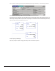
Explicit Messaging with RSLogix 5000® Explicit Messaging within RSLogix 5000® is similar to messaging in RSLogix 500® but there are a few differences; the first is everything is simplified if the tags are predefined. From the Controller Organizer (tree on left) pick Controller Tags and create a tag of Data Type MESSAGE (in this example tag MSG1). Also create a tag that will hold the PLC data that will be written to the MW100 (in this example tag DATATransfer which is a block of 10 floating point numbers).
Next configure the Communication Tab by entering the Path to the MW100. The Path can be designated by the name of the Ethernet port on the PLC (in this case LocalENB – see I/O Configuration below) followed by a comma, with 2 (depth of communications) followed by a comma and the IP address of the MW100 (e.g., 192.168.1.126). Check Connected and Cache Connections to speed up communications to the MW100.
I/O Messaging with RSLogix 5000® The first step in configuring an MW100 to communicate via I/O Messaging is to define a connection within RSLinx®. From the top menu under Communications, pick Configure Drivers.
When prompted, name the driver – in this case MW100 was used but the name can be changed to suit different naming conventions. Path name for Ethernet Device After the driver is named, enter the IP address of the MW100 and click OK to continue. Configuring IP Address of MW100 within RSLinx® When properly configured there should be a new listing in RSLinx® for MW100. Note that when browsing the connection, RSLinx® indicates the node is found.
Open RSLogix 5000® and select the PLC that is going to communicate with the MW100. Right click on Ethernet and select New Module... Adding a New Module to an RSLogix 5000® Project Expand the Communications listing by clicking on the + sign and then scroll down and select ETHERNET-MODULE and click OK.
A definition screen should now appear for the ETHERNET-MODULE. In the Name field – type MW100 (or the desired connection name). Comm Format can be left at Data – DINT and IP Address should be set to the IP address of the MW100. Connection Parameters are where the inputs and outputs are defined. In the Assembly Instance table below there are Instance IDs that correspond to channels within the MW100. All Instance IDs of Kind Producer can be assigned to Input (e.g.
I/O Configuration within Controller Organizer tree – ETHERNET-MODULE MW100 Browsing Controller Tags will now show MW100:I and MW100:O as tags that can be used within controller logic. Clicking on the + sign will expand the selection to show all the points up to the Size specified when defining the input and outputs on the module (e.g., Size 10 = 10 Channels/Tags).
Appendix B – Detailed Configuration of DigiOne IAP Serial Gateway For PLCs that support serial communications via DF1 protocol, there are various gateways that can be used to intercept serial communications and translate to EIP. One such device is the DigiOne IAP®. The IAP has two serial ports and a single Ethernet port. Port 2 on the IAP is a 9 pin d-sub connector that can be connected to the 9 pin d-sub connector on PLC CPUs like the SLC 504® (and others).
Enter the IP address and subnet mask that is desired. Configuring IP Address of DigiOne IAP After configuring the network settings choose Skip and Next on the following two screens and the configuration should be saved to the IAP. The web interface has a wizard that can be used to configure the IAP for industrial networks. On the final screen of the setup utility select Log On to the web user interface of device and click Finish.
The default web browser should pop up with a prompt for a user name and password (if it does not automatically launch the web browser, then open a web browser and browse the IP address of the IAP). The default User Name for the web interface is root and the default Password is dbps. IAP Security Screen After logging, in the main page of the DigiOne IAP web configuration should appear. Select Industrial Automation under Applications to continue.
Select Industrial Automation Wizard link in the center of the screen to configure the IAP for an industrial network. Industrial Automation page Enter a table name for this configuration and then click Next. Table Name for Industrial Automation Setup Select Rockwell/PCCC family and then click Next twice.
The first source that will be setup is the interface for RSLinx® choose Allen-Bradley Ethernet and click Next. Click Next until the following screen shows up and check the Continue creating more message sources box and then click Next. Select Receive messages from serial device connected to a serial port and choose DF1 Full-Duplex for the Protocol and 2 for the Serial port, click Next to continue.
Give the source a Description and configure the serial options to match the configuration of the PLC, then click Next. Click Next until the following screen shows up and then uncheck the Continue creating more message sources box and click Next. When the IAP receives communications, it needs to know where to route the information. To send data to the SLC504® set protocol address to 0.
Address 0 communications need to be retransmitted over the serial port connected to the SLC504®. Set Protocol to DF1 FullDuplex and Serial Port to 2. Click Next to accept defaults until returned to this screen and then check Continue creating more message destinations and Next. Now it is time to route communications to the MW100. In this case, all read and write commands issued from the SLC504® in this example are sent to Node 5 (it could be set to read or write to any other address).
The next step is to tell the IAP where the MW100 is located and how to talk to it. Select Send messages to network device at Hostname – IP Address of MW100. Select EtherNet/IP for the Protocol and then Next. When the Message Destination Protocol Settings screen appears, ensure that Forward Open Connection Path: is left blank. Click Next until the following screen shows up and then uncheck Continue creating more message destinations. Click Next to continue.
If all the settings match on the Summary page, click Finish to save the configuration in the IAP. The IAP will then ask to be rebooted so all the settings can take effect. Once the IAP is rebooted, the DigiOne IAP and attached SLC 504 can now be added as an Ethernet Device (add driver) in RSLinx® (use the IP address of the IAP as the IP address for the Ethernet Device).
Network Solutions Business Division International Sales Dept. Tachihi Bld. No.2, 6-1-3, Sakaecho, Tachikawa-shi,Tokyo 190-8586 Japan Phone: 81-42-534-1413, Facsimile: 81-42-534-1426 YOKOGAWA CORPORATION OF AMERICA (U.S.A.) Phone: 1-770-253-7000 Facsimile: 1-770-251-2088 YOKOGAWA EUROPE B. V. (THE NETHERLANDS) Phone: 31-334-64-1611 Facsimile: 31-334-64-1610 YOKOGAWA ENGINEERING ASIA PTE. LTD. (SINGAPORE) Phone: 65-6241-9933 Facsimile: 65-6241-2606 YOKOGAWA AMERICA DO SUL S. A.