User’s Manual Model SPS24 SENCOM PC Software IM 12A01S02-01E IM 12A01S02-01E 1st Edition
i u Preface Thank you for purchasing the SPS24 SENCOM PC Software. Please read the following respective documents before installing and using the SPS24 SENCOM PC Software. The SPS24 SENCOM PC Software is designed to connect and manage SENCOM sensors for tasks including calibration. For information about the SENCOM sensor, WU11 SENCOM cable, and FLXA21 2-wire analyzer, please refer to their respective manuals.
ii Safety Precautions u n Safety, Protection, and Modification of the Product • In order to protect the system controlled by the product and the product itself and ensure safe operation, observe the safety precautions described in this user’s manual. We assume no liability for safety if users fail to observe these instructions when operating the product. • Modification of the product is strictly prohibited.
iii n Copyright and Trademark Notices The copyrights of online manual contained in the CD are reserved. The online manual is protected by the PDF security from modification, however, it can be output via a printer. Printing out the online manual is only allowed for the purpose of using the product. When using the printed information of the online manual, check if the version is the most recent one by referring to the CD’s version.
iv (3) During the Warranty Period defined above, if the Software Product fails to operate in accordance with the steps of the Instruction Manual etc.
Toc-1 Model SPS24 SENCOM PC Software IM 12A01S02-01E 1st Edition CONTENTS u Preface.............................................................................................................i u Safety Precautions........................................................................................ii 1. Introduction................................................................................................ 1-1 2. 3. 1.1 Outline...............................................................
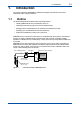
1. 1-1 <1. Introduction> Introduction This section outlines the SENCOM PC Software and explains general items users must understand before using this software. 1.1 Outline The SPS24 SENCOM PC Software has the following features.
1.2 1-2 <1. Introduction> Screen Configuration When launching the SPS24, the Current measurement readings screen appears. Content differs depending on settings or sensor connections. Menu bar (Section 1.2.3) Connection information field (Section 1.2.1) Figure 1.2 Toolbar (Section 1.2.2) Function information field (Section 1.2.
1.2.1 1-3 <1. Introduction> Connection Information Field The connection information field displays the status and information of connected sensors, and can also be used for switching target sensors. Sensors can be connected or disconnected by clicking on the [Connect] or [Disconnect] buttons at the bottom of the field. Toggle between wide/narrow display Connected sensor button Sensor number Model (SensorType) ID(Serial No.) Comments Sensor not connected Target sensor for calibration Figure 1.
1-4 <1. Introduction> 1.2.3 Menu Bar Functions of the menu bar are as shown in Table 1.1. By default, the menu bar is not displayed. It can be turned on or off from the pop-up menu (rightclick to view), or from [Setup] – [Display]. Table 1.
2-1 <2. Preparation and Basic Operation> 2. Preparation and Basic Operation This section describes the procedures for using the SPS24 SENCOM PC Software. l SPS24 system requirements Operating system (OS): Windows 7 SP1 (32 bit/64 bit) or Windows XP Professional SP3 The operating system language and the software language are either English or Japanese. PC hardware: Installed with either of the OSs above and equipped with the CPU and memory listed below.
2-2 <2. Preparation and Basic Operation> 3. Click on “Install the interface box driver”. 4. The “User Account Control” screen is displayed. Click “Yes” to continue. 5. The “Welcome to Yokogawa Driver for interface box setup” screen is displayed. Click “Next” to continue. 6. The “Ready to Install the Program” message appears. Click “Install”. 7. The “Windows Security” screen appears. Click “Install”. (USB device driver) 8. The “Windows Security” screen appears. Click “Install”.
2-3 <2. Preparation and Basic Operation> l Connecting a USB cable for the interface box For Windows XP installation, connect a cable for the interface box to a USB port on the PC and install a COM port driver. For multiple interface boxes, installation is required for every new connection. 1. Inserting a cable for the interface box to a USB port on the PC automatically displays the “Hardware Update wizard”. Select “Install the software automatically (Recommended)” and click “Next”. 2.
3. 2-4 <2. Preparation and Basic Operation> “License Agreement” appears. Read the terms on the license agreement. Select “I accept the terms in the License Agreement” and click “Next”. (Selecting “I do not accept the terms in the License Agreement” aborts SPS4 installation. Click “Cancel” to leave the installation.) 4. The “User information” screen is displayed. Enter the user name and organization, and click “Next”. 5. The “Install destination” screen appears.
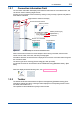
2.4 2-5 <2. Preparation and Basic Operation> Sensor Connection For information on how to connect FU20F SENCOM sensors and WU11 SENCOM cables, refer to IM 12B06J03-04E. For the FLXA21 2-wire liquid analyzer, refer to IM 12A01A02-01E. FLXA21 WU11 SENCOM cable Connector connection SENCOM sensor Windows PC USB cable * Interface box * WU11 SENCOM cable (3m) * SPS24 SENCOM PC Software *: SPS24 accessory Figure 2.
2.5 2-6 <2. Preparation and Basic Operation> How to use the SPS24 Go to Windows [Start] – [All Programs] – [Yokogawa SENCOM PC Software] and click “SENCOM PC Software” to launch the SPS24. l First launch At first launch, the “Please set RS port” message appears. Click “OK” to close the dialog box. Confirm the sensor connection and go to [Setup] – [RS port No.] to assign the RS port number to the sensor. Toolbar Select USB RS-485 Port. Click to save. Connection information field Figure 2.
Figure 2.3 2-7 <2. Preparation and Basic Operation> Example of RS port number view (2 sensors are connected simultaneously) l Subsequent Launches (connections) Connect the SENCOM sensor first and then launch SPS24. The sensor connection is automatically detected when the program launches. The RS port number setting is retained. To connect the SENCOM sensor after the SPS24 launch, click [Connect] in the connection information field.
3-1 <3. Sensor Management> 3. Sensor Management Clicking on [Sensor management] from the toolbar will display “Current measurement readings,” which shows the measurement value of sensors connected to the PC. With this function, users can view sensor measurements, adjust sensor performance and settings, or calibrate sensors. By default, measurement targets and calibration objects are as shown in Table 3.1. Table 3.
3.2 3-2 <3. Sensor Management> [Sensor setup] Clicking on [Sensor setup] in “Current measurement readings” will display the sensor setting screen, where settings can be applied to each sensor individually. For the settings common to pH sensors, go to the pH/ORP common setting in [Setup]. This screen displays values stored in connected sensors. Changed values will be displayed in red. Click on [Synchronize] to send the new setting to SENCOM sensors.
3.3 <3. Sensor Management> 3-3 [Start calibration] Clicking on [Start calibration] in “Current measurement readings” will display the selection screen that shows sensors to be calibrated. Sensors of the same model and type can be calibrated simultaneously. When a sensor is selected, the upper part of the sensor button turns blue for identification. Before pH measurement, calibrate the pH sensor with the standard solution. Before ORP measurement, check the electrode as regular maintenance.
3-4 <3. Sensor Management> l Zero/slope1,2(3point) This calibration type is the line-segment type three-point calibration. If the relation between electromotive force and pH is not in proportion for a wide range, divide the relevant range into two sections and obtain the zero (asymmetry) and slope (sensitivity) in each section to perform calibration. Limitations • Three different buffer solutions whose difference in pH value between buffer solutions is 1 pH or more should be used.
3-5 <3. Sensor Management> Limitations • Three different buffer solutions whose difference in pH value between buffer solutions is 1 pH or more should be used. (1st buffer < 2nd buffer < 3rd buffer or 1st buffer > 2nd buffer > 3rd buffer) • The temperature difference between the 1st and 2nd buffer solutions should be 20ºC or less. • The temperature difference between the 2nd and 3rd buffer solutions should be 20ºC or less. Table 3.
4. <4. Database Viewer> 4-1 Database Viewer Clicking on [Database viewer] from the toolbar will display up-to-date information about the sensors connected to the SPS24. From this screen, the information database for sensors can be managed. Kind of sensor Tool menu Checkbox Calibration history menu File menu Figure 4.1 Example of Database Viewer screen The “Sensor” field indicates the sensor numbers of sensors currently connected to the PC.
4-2 <4. Database Viewer> l [Add ID] Add ID is available only for non-digital pH/ORP sensors. Use this function for managing data of non-digital pH/ORP sensors in the database. Register new ID data. Add or change data by clicking on fields shown in boxes and save the changes. l [Delete ID] This function deletes sensor ID data that was selected with a checkbox. Sensor ID data of any connected sensors cannot be deleted. To delete multiple data, tick on “□ Do this for all current items.
4-3 <4. Database Viewer> l [Export] Generates a backup file to save the data. Choose whether to save the entire data or individual data (select with a checkbox). Enter the file name (the default name is smart1_(yymmddhhmmss).smf) and save the file. l [Import] Imports a backup file that was generated with [Export]. Import is not required when operation is normal. Data of connected sensors cannot be imported. Select the target file and choose whether to import the entire data or individual data.
5. 5-1 <5. Error Information> Error Information When an error occurs, the color of [Error information] on the toolbar changes and an icon starts to flash. Clicking on [Error information] displays the error that is occurring in the connected sensor. The error information screen displays the error that is occurring in any connected sensors, and any error or warning for the SPS24 itself. Errors are more critical than warnings. Clicking on the error or warning information displays the actions required.
6. 6-1 <6. Setup> Setup Configures various settings. For details about setting, refer to User’s Manual of Model FLXA21 2-Wire Analyzer (IM 12A01A02-01E). Clicking [Setup] on the toolbar takes you to the setup screen. Clicking on each function takes you to the corresponding setting field. Each function can also be accessed from “Tool” on the menu bar. Click “Save” to store the change. Function menu Figure 6.
6-2 <6. Setup> The file name can be up to 255 single-byte characters (127 double-byte characters). A file name cannot contain any of the following characters: + * / ? ” < > | l [Initialize] Initializes the settings. Does not include: RS Port Number, Select Language, and User Account settings Includes: [Select column] setting of the database viewer 6.1 6.2 RS Port Number Configures the RS port number of each USB-RS485 conversion cable.
6-3 <6. Setup> By default, the user account option is disabled (Level 4). See below for more details about levels. When this option is enabled, the Level 4 user account information screen is displayed for the purpose of confirmation. Entering the user ID and password changes the level to Level 1 and the Current measurement readings appears. One user is registered by default. A001 User ID: Level: 4 Operator: User Password: 123456 To enable password management, use the above user ID and password.
Table 6.2 Levels and available functions Function Sensor Display management measurements Display performance Set sensors Calibrate Database Display the sensor viewer database Edit the sensor database Print the database Import/export the database Setup Set user accounts Initialize the setup Import/export the setup configuration Set other configurations Error Display error information information Clear error information A: Available 6.7 6-4 <6.
6-5 <6. Setup> Table 6.
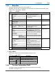
<6. Setup> Temperature Reference temperature compensation Process pH Temp. compensation Setup Error display Define SENCOM diagonostic reference -30.0 to 140.0 degC -22.0 to 284.0 degF None, Temp. coefficient, Matrix, NEN6411 -0.100 to 0.100 pH/ degC -0.1 to 0.1 pH/degF Matrix settings.. Temperature range: -30.0 to 140.0 degC -22.0 to 284.0 degF pH: -2.00 to 20.00 pH ORP None, Temp. coefficient Setup -10.00 to 10.00 mV/ degC -5.6 to 5.
6-7 <6. Setup> Table 6.4 1. * 2. 3. 4. 5. 6. 7. 8. 9. 10. 11. 12. 13. 14. 15. 16. 17. * *: Initial values of “Setting for user defined buffer” 0.0 degC 5.0 degC 10.0 degC 15.0 degC 20.0 degC 25.0 degC 30.0 degC 35.0 degC 40.0 degC 45.0 degC 50.0 degC 55.0 degC 60.0 degC 65.0 degC 70.0 degC 75.0 degC 80.0 degC 32.0 degF 41.0 degF 50.0 degF 59.0 degF 68.0 degF 77.0 degF 86.0 degF 95.0 degF 104.0 degF 113.0 degF 122.0 degF 131.0 degF 140.0 degF 149.0 degF 158.0 degF 167.0 degF 176.
7. 7-1 <7. Account> Account The [Account] option is only available when [Setup] – [User account] (User account) is enabled. Initial level is set at Level 1. For more information on levels, see “Table 6.2 Levels and available functions”. Clicking on [Account] of the toolbar displays the user account screen (when the logged-in user is not of Level 4). Enter the user name and password and log in. If an incorrect user name or password is entered 3 times, the user account screen closes.
i Revision Record Manual Title : Model SPS24 SENCOM PC Software Manual No. : IM 12A01S02-01E May 2013/1st Edition Newly published Yokogawa Electric Corporation 2-9-32 Nakacho, Musashino-shi, Tokyo 180-8750, JAPAN Homepage: http://www.yokogawa.