
Instruction Manual


IM 11M12A01-03E
5-15
5. Wiring
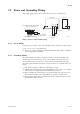
5.8 Wiring for Contact Input
The converter can execute specified function when receiving contact signals.
To use these contact signals, wire as follows:
Converter Terminal box
DI-1
DI-C
DI-2
Contact input 1
Contact input 2
F5.14E.EPS
Figure 5.14 Contact Input Wiring
5.8.1 Cable Specifications
Use a 2-core or 3-core cable for this wiring. Depending on the number of input(s),
determine which cable to use.
5.8.2 Wiring Procedure
(1) M4 screws are used for the terminals of the converter. Each cable should be termi-
nated in the corresponding crimp-on terminals.
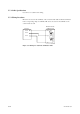
(2) The ON/OFF level of this contact input is identified by the resistance. Connect a
contact input that satisfies the specifications in Table 5.2.
Table 5.2 Identification of Contact Input ON/OFF
T5.2E.EPS
Closed Open
Resistance
200V or less 100 kV or more