
Instruction Manual


IM 11M12A01-03E
5-12
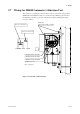
5.6 Wiring for Contact Output
Contact outputs 1 to 3 can be freely assigned to "low limit alarm", "high limit alarm",
etc. user selectable, but the assignment of contact output 4 is fixed ("error output"). And
the action (contact closed on error output) also cannot be changed.
When using these contact outputs, install the wiring as follows:
#1 Output
#2 Output
#3 Output
#4 Output
DO-1
DO-1
DO-2
DO-2
DO-3
DO-3
Terminal box Annunciator or the like
F5.11E.EPS
Converter
DO-4
DO-4
Figure 5.11 Contact output wiring
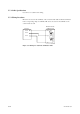
5.6.1 Cable Specifications
Number of wires in cable varies depending on the number of contact used.
5.6.2 Wiring Procedure
(1) M4 screws are used for the terminals of the converter. Each wire in the cable should
be terminated in the corresponding crimp-on terminal.
(2) The capacities of the contact output relay are 30 V DC 3 A, 250V AC 3 A. Connect
a load (e.g. pilot lamp and annunciator) within these limits.