
Instruction Manual


IM 11M12A01-03E
5-10
5.4 Wiring for Analog Output
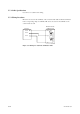
This wiring is for transmitting 4 to 20 mA DC output signals to a device, e.g. recorder.
Maintain the load resistance including the wiring resistance at 550V or less.
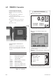
Shielded cable
Receiver 1
Receiver 2
Converter
1
2
1
2
AO1(+)
AO1(-)
AO2(+)
AO2(-)
FG
F5.9E.EPS
Figure 5.9 Wiring for analog output
5.4.1 Cable Specifications
For this wiring, use a 2-core or a 4-core shielded cable.
5.4.2 Wiring Procedure
(1) M4 screws are used for the terminals of the converter. Each wire of the cable should
be terminated in corresponding crimp-on terminals. Ensure that the cable shield is
connected to the FG terminal of the converter.
(2) Be sure to connect “+” and “-” polarities correctly.