
Instruction Manual


IM 11M12A01-03E
5-8
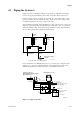
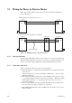
5.3 Wiring for Power to Detector Heater
This wiring provides electric power from the converter to the heater for heating the
sensor in the detector.
Detector Converter
(1) Ambient temperature of the detector: 808C or less
(2) Ambient temperature of the detector: exceeding 808C
Heat-resistant wiring
HTR 7
HTR 8
HTR 7
HTR 8
HEATER
HEATER
Terminal box
F5.7E.EPS
Detector Converter
Figure 5.7 Wiring for power to the detector heater
5.3.1 Cable Specifications
Basically, PVC insulated PVC sheathed control cables (2 cores) are used for this wiring.
When the ambient temperature of the detector exceeds 808 C, install a terminal box, and
connect to the detector using six 600V silicon rubber insulated glass braided wires.
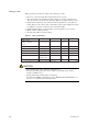
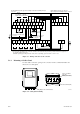
5.3.2 Connection to Detector
When connecting the cable to the detector, proceed as follows:
(1) Mount cable glands or conduits of the specified thread size to the wiring connections
of the detector.
The detector may need to be removed in future for maintenance, so be sure to allow
sufficient cable length.
(2) If the ambient temperature at the location of wire installation is 80 to 1508 C, be sure
to use a flexible metallic conduit for the wire. If a non-shielded 0 600V silicon rubber
insulated glass braided wire 0 is used, keep the wire away from noise sources, to
avoid noise interference.
(3) The size of the terminal screw threads is M3.5. Each cable should be terminated in
the corresponding size crimp-on terminals (*1) respectively.
*1 If the ambient temperature at the detector installation site exceeds 608 C, use a 0 bare
crimp-on terminal0 .