
Instruction Manual


IM 11M12A01-03E
5-5
5. Wiring
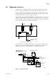
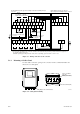
5.2 Wiring for Detector Output
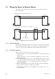
This wiring enables the converter to receive cell output from the detector, output from a
thermocouple and a reference junction compensation signal. Install wires that allow for
10 V of loop resistance or less. Keep detector signal wiring away from power wiring.
Separate the signal and the power wiring.
CELL(+)
CELL(+)
CELL(-)
CELL(-)
TC(+)
TC(+)
TC(-)
TC(-)
CJ(+)
CJ(+)
CJ(-)
CJ(-)
FG
Shielded cables
Shielded cables
Detector Converter
CELL(+)
CELL(+)
CELL(-)
CELL(-)
TC(+)
TC(+)
TC(-)
TC(-)
CJ(+)
CJ(+)
CJ(-)
CJ(-)
FG
Detector Converter
(2) Ambient temperature of the detector: exceeding 808C
Heat-resistant wiring
Terminal box
(1) Ambient temperature of the detector: 808C or less
F5.5E.EPS
Figure 5.5 Wiring for detector output
CAUTION
If shielded cables cannot be used between the detector and the terminal box, for ex-
ample, when heat-resistant wiring is used, locate the detector and the terminal box as
close together as possible.
5.2.1 Cable Specifications
Basically, PVC sheathed PVC insulated cable (six core) is used for this wiring. When
the ambient temperature of the detector exceeds 80°C, install a terminal box, and
connect with the detector using six-piece 600-V silicon rubber insulated glass braided
wire.