
Instruction Manual


IM 11M12A01-03E
4-3
4. Piping
4.2 Piping for System 2
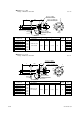
Piping in System 2 is illustrated in Figure 4.7.
~
EXA
ZR402G
Separate type Zirconia
High Temperature Humidity Analyzer
Model ZR22G Detector
Model ZR402G Converter
Stop valve
or Check valve
Model ZA8F flow setting unit
Reference
gas
Calibration gas
Needle
valve
Flowmeter
Instrument air
Air Set
Calibration gas pressure regulator
Zero gas
cylinder
Calibration gas
unit case
F4.7E.EPS
Span gas (Same as Zero gas
Calibration unit)
100 to 240 V AC
Contact input
Analog output, contact output
Digital output (HART)
Signal
(6-core shield cable)
Heater (2-core)
Figure 4.7 Piping for System 2
Piping in System 2 is as follows:
• Place a stop valve or check valve through the nipple at the calibration gas inlet of the
detector.
• It is recommended to use ZH21B dust protector to protect the probe output from dust
agitation (i.e., to prevent combustible materials from entering the probe cell) where
humidity measurements are made under dusty or combustible environment
4.2.1 Piping Parts for System 2
Check that the parts listed in Table 4.2 are ready.
Table 4.2
Detector Piping location Parts Note
General-use Calibration gas inlet Stop valve or check valve Recommended by YOKOGAWA
detector (L9852CB or G7016XH)
Provided by YOKOGAWA
(K9292DN or K9292DS)
Nipple * Rc1/4 or 1/4 NPT generic parts
Zero gas cylinder User's scope
Gas pressure regulator Recommended by YOKOGAWA
(G7013XF or G7014XF)
Joint for tube connection Rc1/4 or 1/4 NPT generic parts
Reference gas inlet Air set Recommended by YOKOGAWA
(K9473XH/K9473XJ or
G7004XF/ K9473XG)
Joint for tube connection Rc1/4 or 1/4 NPT generic parts
Note : Parts with marking * are used when required.
T4.2E.EPS