User's Manual Model ZR22G, ZR402G Separate type Zirconia High Temperature Humidity Analyzer IM 11M12A01-03E IM 11M12A01-03E 7th Edition
Introduction The EXAxt ZR Separate-type Zirconia High-temperature Humidity Analyzer has been developed for humidity control in various industrial processes. This analyzer basically consists of a detector and a converter. You can select between several versions based upon your application. Optional accessories are also available to improve measurements and automate calibration. An optimal control system can be realized by adding appropriate options.
This manual consists of twelve chapters. Please refer to the reference chapters for installation, operation and maintenance. Table of Contents Chapter Outline 1. Overview Equipment models and system configuration examples 2. Specifications Standard specification, model code (or part number), 3. Installation dimension drawing for each equipment Installation method for each equipment 4. Piping Examples of piping in three standard system 5.
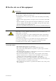
r For the safe use of this equipment CAUTION The cell (sensor) at the tip of the detector is made of ceramic (zirconia element). Do not drop the detector or subject it to pressure stress. • Do NOT allow the sensor (probe tip) to make contact with anything when installing the detector. • Avoid any water dropping directly on the probe (sensor) of the detector when installing it. • Check the calibration gas piping before introducing the calibration gas to ensure that there is no leakage of the gas.
(2) Safety and Modification Precautions • Follow the safety precautions in this manual when using the product to ensure protection and safety of personnel, product and system containing the product. (3) The following safety symbols are used on the product as well as in this manual. DANGER This symbol indicates that the operator must follow the instructions laid out in this manual in order to avoid the risk of personnel injuries or fatalities such as electric shock.
• Special descriptions in this manual This manual indicates operation keys, displays and drawings on the product as follows: • Operation keys, Enclosed in [ ], displays on the panel 0 0. (Ex. [MODE] key) (Ex. message display (Ex. data display 0 BASE 0) 0 102 0 lit, 0 102 0 flashing) • Drawing for flashing Indicated by gray characters.
r NOTICE • Specification check When the instrument arrives, unpack the package with care and check that the instrument has not been damaged during transportation. In addition, please check that the specification matches the order, and required accessories are not missing. Specifications can be checked by the model codes on the nameplate. Refer to Chapter 2 Specifications for the list of model codes.
d Yokogawa does not warrant conformance with the specific application at the user site. Yokogawa will not bear direct/indirect responsibility for damage due to a specific application. d Yokogawa Electric will not bear responsibility when the user configures the product into systems or resells the product. d Maintenance service and supplying repair parts will be covered for five years after the production ends.
Contents Introduction ........................................................................................................................... i r For the safe use of this equipment ............................................................................... iii r NOTICE ......................................................................................................................... vi r After-Sales Warranty ......................................................................................
3.2 Installation of the Converter ........................................................................... 3-4 3.2.1 Location .................................................................................................. 3-4 3.2.2 Mounting of the Converter ...................................................................... 3-4 3.3 Installation of ZA8F Flow Setting Unit ......................................................... 3-7 3.3.1 Location ....................................................
5.8 Wiring for Contact Input ............................................................................... 5-15 5.8.1 Cable Specifications .............................................................................. 5-15 5.8.2 Wiring Procedure ................................................................................... 5-15 5.9 Temperature Input Wiring ............................................................................ 5-16 5.9.1 Applicable Temperature Transmitter ......................
8.3 Alarm Setting .................................................................................................. 8-9 8.3.1 Alarm Values ........................................................................................... 8-9 8.3.2 Alarm Output Actions ............................................................................. 8-9 8.3.3 Alarm Setting Procedure ....................................................................... 8-10 8.3.4 Default Values ......................................
11. Inspection and Maintenance .................................................................................... 11-1 11.1 Inspection and Maintenance of the Detector ................................................ 11-2 11.1.1 Cleaning the Calibration Gas Tube ....................................................... 11-2 11.1.2 Replacing the Sensor Assembly ............................................................ 11-3 11.1.3 Replacement of the Heater Unit ..............................................
1. Overview 1. Overview The EXAxt ZR Separate-type Zirconia High-temperature Humidity Analyzer is used to measure the humidity of hot gases continuously in driers which use hot gas or electricity as the heat source. It can also be used in a variety of manufacturing applications in humidifiers, as well as in driers, for humidity measurement and control. It can help improve productivity in these application fields.
1.1 < EXAxt ZR > System Configuration The system configuration should be determined by the conditions; e.g. whether the calibration gas flow should be automated. The system configuration can be classified into three basic patterns as follows: 1.1.1 System 1 This is the simplest system consisting of a detector and a converter. This system can be implemented for monitoring humidity in a production process such as food production.
1. Overview 1.1.2 System 2 This system is for accurate monitoring and controlling humidity when the installation environment is polluted with gases other than the air. Instrument air (clean and dry air of oxygen concentration 21%) is used for the reference gas and the span gas for calibration. Zero gas is fed in from a cylinder during calibration. The gas flow is controlled by the ZA8F flow setting unit (for manual valve operation).
1.1.3 System 3 This system is for accurate monitoring and controlling of humidity. Instrument air (clean and dry air) is used for the reference gas and the span gas for calibration. Zero gas is fed in from a cylinder during calibration. The calibration gas flow is controlled automatically by the ZR40H automatic calibration unit. This system is similar to system 2, except that the calibration gas flow is automated using the ZR40H automatic calibration unit.
1. Overview 1.2 < EXAxtZR > System Components 1.2.1 System Components Model or Part No.
2. Specifications 2. Specifications This chapter describes the specifications for the following: ZR22G General-use separate-type detector (See Section 2.2.1) ZH21B Dust protector ZR402G Separate-type converter ZA8F Flow setting unit (See Section 2.4.1) ZR40H Automatic calibration unit (See Section 2.4.2) ZO21S Standard gas unit (See Section 2.5) 2.1 General Specifications 2.1.1 Standard Specifications (See Section 2.2.2) (See Section 2.
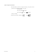
Repeatability: (Note1) 61 vol% H2O (sample gas pressure 2 kPa or less) Linearity: (Excluding standard gas tolerance) (Note1) (Use oxygen of known concentration (in the measuring range) as the zero and span calibration gas.) 62 vol% H2O; (Sample gas pressure: within 60.49 kPa) 63 vol% H2O; (Sample gas pressure: 2 kPa or less) Drift: (Excluding the first two weeks in use) (Note1) both zero and span 63 vol% H2O/month Response Time: Response of 90 % within 5 seconds.
2. Specifications 2.2 General-use Separate-type Detector and Related Equipment The “Detector with dust protector” consists of ZR22G general-use separate-type detector and ZH21B dust protector (refer to Section 2.2.2). 2.2.1 ZR22G General-use Separate-type Detector Sample Gas Temperature: 0 to 7008 C (Probe only) It is necessary to mount the cell using Inconel cell-bolts when the temperature is 6008 C or greater.
Probe Mounting Angle: Horizontal to vertically downward. When the probe insertion length is 2 m or less, installing at angles from horizontal to vertically downward is available. When the probe insertion length exceeds 2.5 m, mount vertically downward (within 658 ) and use a probe protector. Weight: Insertion length of 0.4 m: approx. 6 kg (JIS 5K 65) / approx. 11 kg (ANSI 150 4) Insertion length of 1.0 m: approx. 8 kg (JIS 5K 65) / approx. 13 kg (ANSI 150 4) Insertion length of 1.5 m: approx.
2. Specifications Model and Codes Model [ Style : S2 ] Suffix code Option code Description Separate type Detector of Zirconia High Temperature Humidity Analyzer 0.4 m Length -040 0.7 m -070 1.0 m -100 1.5 m -150 2.0 m -200 2.5 m (*1) -250 3.
EXTERNAL DIMENSIONS Model ZR22G Detectors Separate type Zirconia High Temperature Humidity Analyzer L 283 to 292 85 [124 [50.8 t L=0.15, 0.4, 0.7, 1.0, 1.5, 2.0, 2.5, 3.0 (m) Rc1/4 or 1/4NPT Reference air inlet 155 to 163 69 C 2-G1/2,2-1/2NPT etc.
2. Specifications Model ZR22G...-P Detectors(with pressure compensation), Separate type Zirconia High Temperature Humidity Analyzer, Detectors 303 L 85 f124 f50.8 t L=0.15, 0.4, 0.7, 1.0, 1.5, 2.0, 2.5, 3.0 (m) Rc1/4 or 1/4NPT Reference air inlet L 156 87 C 2-G1/2, 2-1/2NPT etc.
2.2.2 ZH21B Dust Protector This protector is designed to protect the probe output from dust agitation (i.e., to prevent combustible materials from entering the probe cell where humidity measurements are made) in a dusty environment. d Standard Specification Insertion length: 0.428m Flange: JIS 5K 80 FF SUS304 or ANSI Class 150 4 FF SUS304 (However, flange thickness is different) Material: SUS 316(JIS), SUS 304(JIS) (flange) Weight: Approximately 6kg (JIS), approximately 8.
2. Specifications 2.3 ZR402G Separate-type Converter 2.3.1 Standard Specifications Operated using an LCD touchscreen on the converter. Display: LCD display of size 320 by 240 dot with touchscreen.
2.3.2 Function Display Functions: Value Display; Displays values of the measured Oxygen concentration, moisture quantity, mixture ratio etc. Graph Display; Displays trends of measured oxygen concentration moisture quantity, mixture ratio etc. Data Display;Displays various useful data for maintenance, such as cell temperature, reference junction temperature, maximum/ minimum moisture quantity and the like. Status Messages; Indicates an alarm or error occurrence with flashing of the corresponding icon.
2.
Contact Output: Four points, contact capacity 30V DC 3A, 250V AC 3A (resistive load). Three of the output points can be selected to either normally energized or normally de-energized status. Delayed functions (0 to 255 seconds) and hysteresis function (0 to 9.9 vol% O2 can be added to high/low-alarms. The following functions are programmable for contact outputs.
2. Specifications d Model and Suffix Codes Model Suffix code Option code Description Separate type Zirconia High Temperature Humidity Analyzer, Converter ZR402G -P -G -M -T Display -J -E -G -F Instruction manual -J -E G1/2 Pg13.5 M20x1.5 mm 1/2NPT Japanese English German French Converter thread Japanese English Always -A -A Options Tag plates /HS /H /SCT Set for Humidity Analyzer (*3) /PT Printed tag plate Hood (*2) Stainless steel tag plate (*1) *1 Specify either /SCT or /PT option code.
d External Dimensions Unit ;mm 1 to 6 (Panel Thickness) 2-inch mounting pipe 4 - f 6 holes for Wall mounting 120.2 8 10 57.3 228 36 54.7 136.3 (1/2NPT) 100 126.5 280 EXA ZR402G 111 40 40 40 46 23 8-G1/2, 8-1/2NPT etc (Wiring connection) 38 24 14 38 ( for wall mounting) 126.5 274 +2 0 4 - f 6 holes 4-R8 to R10 or 4-C5 to C8 +2 0 190 183 Wall mounting Panel Cut-out F2.5E.EPS d Accessories 2-14 Item Fuse Bracket for mounting Part. No.
2. Specifications d Hood (Option / H) 243 62 123 64 205.5 63 64 155.5 63 39 62 55 Unit ;mm 94.5 251.
2.4 ZA8F Flow Setting Unit and ZR40H Automatic Calibration Unit 2.4.1 ZA8F Flow Setting Unit This flow setting unit is applied to the reference gas and the calibration gas in a system configuration (System 2). This unit consists of a flow meter and flow control valves to control the flow of calibration gas and reference air. • Standard Specifications FIowmeter: Calibration gas; 0.1 to 1.0 l/min. Reference air; 0.1 to 1.0 l/min.
2. Specifications d External Dimensions Unit: mm f6 hole 180 7 140 REFERENCE CHECK ZERO SRAN Zero gas outlet Span gas inlet Zero gas inlet 26 Reference air outlet 222.8 235.8 REFERENCE 20 35 35 35 35 20 8 35 70 4-Rc1/4 Piping connection port Instrument air inlet CHECK OUT Flow meter ZERO GAS IN SPAN GAS IN REF OUT Flow meter AIR IN Instrument air Approx 1.5 l/min. Airset Air pressure: without check valve ; measured gas pressure 1 approx.
2.4.2 ZR40H Automatic Calibration Unit This automatic calibration unit is applied to supply specified flow of reference gas and calibration gas during automatic calibration to the detector in a system configuration (System 3). • Specifications Used when auto calibration is required for the separate type and instrument air is provided. The solenoid valves are provided as standard.
2. Specifications d External Dimensions Unit : mm wiring inlet ; 2-G1/2,Pg13.5,M2031.5 or 1/2NPT(Female) 2B pipe mounting example (wiring inlet is at same position on rear) *1 with four M6 screws can wall-mount 90 26 116.5 54 71.5 *1 41.2 4- f 140 6.5 12 41.2 49.
Piping REF OUT CHECK OUT EV1 ZERO GAS IN flow meter flow meter *2 *2 EV2 AIR IN Instrument air Approx. 1.5 l/min. *2 Needle valve is supplied as accessory with flow meter. F2.6-3E.
2. Specifications 2.5 ZO21S Standard Gas Unit This is a handy unit to supply zero gas and span gas to the detector in a system configuration based on System 1. It is used in combination with the detector only during calibration. d Standard Specifications Function: Portable unit for calibration gas supply consisting of span gas (air) pump, zero gas cylinder with sealed inlet, flow rate checker and flow rate needle valve. Sealed Zero Gas Cylinders (6 provided): E7050BA Capacity: 1 l Filled pressure: Approx.
d External Dimensions 253 228 92 Unit : mm Flow checker Span gas valve Zero gas valve 1600 Gas outlet 354 Zero gas cyilnder (6 cyilnder): E7050BA F2.7E.EPS 2.6 Other Equipment 2.6.1 Stop Valve (Part Number: L9852CB or G7016XH) This valve is mounted on the calibration gas line in the system to allow for one-touch calibration. This applies to the system configuration shown for system 1 in section 1. Standard Specifications Connection: Rc 1/4 or 1/4 FNPT Material: SUS 316 (JIS) Weight: Approx.
2. Specifications 2.6.2 Check Valve (Part Number: K9292DN or K9292DS) This valve is mounted on the calibration gas line (directly connected to the detector). This is applied to a system based on the (System 2 and 3) system configuration. This valve prevents the process gas from entering the calibration gas line. Although it functions as a stop valve, operation is easier than a stop valve as it does not require opening/closing at each calibration.
2.6.3 Air Set Part Number: K9473XH or K9473XJ This set is used to lower the pressure when instrument air is used as the reference and span gases. Standard Specifications Primary Pressure: Max. 2 MPa G Secondary Pressure: 0 to 0.25 MPa G Connection: Rc1/4 or 1/4FNPT (includes joint adapter) Weight: Approx.1 kg Description Part No. K9473XH Joint: Rc 1/4, Material: Aluminum K9473XJ Joint: 1/4 NPT (F) , Material: Body; Aluminum, Adapter; Zinc alloy T2.11E.
2. Specifications Part Number; G7004XF or K9473XG Primary Pressure: Max. 1 MPa G Secondary Pressure: 0.02 to 0.5 MPa G Connection: Rc1/4 or 1/4 FNPT with joint adapter Part No. Description G7004XF Joint: Rc 1/4, Material: Zinc Alloy K9473XG Joint: 1/4 NPT (F) , Material: Body; Zinc Alloy, Adapter; SUS316 T2.13E.EPS d External Dimensions Unit : mm View A Panel cut dimensions Horizontal mounting 22 Vertical mounting [15 40 +0.5 2-2.2 -0 40 2-[6.5 max.
2.6.4 Zero-gas Cylinder (Part Number: G7001ZC) The gas from this cylinder is used as the calibration zero gas and detector purge gas. Standard Specifications Capacity: 3.4 l Filled pressure: 9.8 to 12 MPa G Composition: 0.95 to 1.0 vol% O2 in N2 (Note) Export of such high pressure filled gas cylinders to most countries is prohibited or restricted. 325 485 Unit : mm [140 2.6.5 Weight : Approx. 6 kg F2213.
2. Specifications 2.6.6 Case Assembly for Calibration-gas Cylinder (Part Number: E7044KF) This case is used to store the zero gas cylinders. Standard Specifications Case Paint: Baked epoxy resin, Jade green (Munsell 7.5 BG 4/1.5) Installation: 2B pipe mounting Material: SPCC (Cold rolled steel sheet) Weight: Approx. 3.6kg, 10 kg with gas cylinder (Note) Export of such high pressure filled gas cylinders to most countries is prohibited or restricted.
2.6.7 Model ZR22A Heater Assembly Table 2.1 ZR22A Style: S2 Model Suffix code Length (p1) Description Option code Heater Assembly for ZR22G ZR22A 0.15 m 0.4 m 0.7 m 1m 1.5 m 2m 2.
3. Installation 3. Installation This chapter describes installation of the following equipment: 3.1 Detector 3.2 Converter 3.3 ZA8F Flow Setting Unit 3.4 ZR40H Automatic Calibration Unit 3.5 E7044KF Case Assembly for Calibration-gas Cylinder 3.1 Installation of the Detector 3.1.1 Location The following should be taken into consideration when installing the detector: (1) Easy and safe access to the detector for checking and maintenance work.
3.1.2 Probe Insertion Hole Includes those analyzers equipped with a dust protector. When preparing the probe insertion hole, the following should be taken into consideration: CAUTION • The outside dimension of detector may vary depending on its options. Use a pipe that is large enough for the detector. Refer to Figure 3.1 for the dimensions. • If the detector is mounted horizontally, the calibration gas inlet and reference gas inlet should face downwards.
3. Installation 3.1.3 Installation of the Detector CAUTION • The cell (sensor) at the tip of the detector is made of ceramic (zirconia). Do not drop the detector, as impact will damage it. • A gasket should be used between the flanges to prevent gas leakage.
3.2 3.2.1 Installation of the Converter Location The following should be taken into consideration when installing the converter: (1) Readability of the indicated values of moisture concentration or messages on the converter display. Easy and safe access to the converter for operating keys on the panel. (2) Easy and safe access to the converter for checking and maintenance work. (3) An ambient temperature of not more than 558C and little change in temperature (recommended within 158C in a day).
3. Installation (1) Drill mounting holes through the wall as shown in Figure 3.4. Unit: mm Four holes 6 mm in diameter or M5 screw 126.5 190 F3.8E.EPS Figure 3.4 Mounting holes (2) Mount the converter. Secure the converter on the wall using four screws. Note: For wall mounting, the bracket and bolts are not used. F3.5E.EPS Figure 3.
(1) Cut out the panel according to Figure 3.6. Unit: mm +2 274 0 +2 183 0 F3.6E.EPS Figure 3.6 Panel cutout sizes (2) Remove the fitting from the converter by loosening the four screws. (3) Insert the converter case into the cutout hole of the panel. (4) Attach the mounting fitting which is once removed in step (2) again to the converter. (5) Firmly fix the converter to the panel. Fully tighten the two clamp screws to hold the panel with the fitting.
3. Installation 3.3 Installation of ZA8F Flow Setting Unit 3.3.1 Location The following should be taken into consideration: (1) Easy access to the unit for checking and maintenance work. (2) Near to the detector and the converter for operating keys on the panel. (3) No corrosive gas. (4) An ambient temperature of not more than 558C and little changes of temperature. (5) No vibration. (6) Little exposure to rays of the sun or rain. 3.3.
(1) Make a hole in the wall as illustrated in Figure 3.9. Unit : mm 223 140 4 - f6 hole, or M5 screw F3.9E.EPS Figure 3.9 Mounting holes (2) Mount the flow setting unit. Remove the pipe mounting parts from the mount fittings of the flow setting unit and attach the unit securely on the wall with four screws. F3.10E.EPS Figure 3.
3. Installation 3.4 Installation of ZR40H Automatic Calibration Unit 3.4.1 Location The following should be taken into consideration: (1) (2) (3) (4) (5) (6) 3.4.2 Easy access to the unit for checking and maintenance work. Near to the detector and the converter No corrosive gas. An ambient temperature of not more than 558C and little change of temperature. No vibration. Little exposure to rays of the sun or rain.
(1) Make a hole in the wall as illustrated in Figure 3.12. Unit : mm 223 140 4 - f6.5 hole, or M6 screw F3.12E.EPS Figure 3.12 Mounting holes (2) Mount the Automatic Calibration Unit. Remove the pipe mounting parts from the mount fittings of the flow setting unit and attach the unit on the wall with four screws. When setting it with M5 bolts, use washers. 4-[6.5 F3.13E.EPS Figure 3.
3. Installation 3.5 Installation of E7044KF Case Assembly for the Calibration-gas Cylinder The calibration gas unit case is used to store the G7001ZC zero gas cylinders. 3.5.1 Location The following should be taken into consideration: (1) Easy access for cylinder replacement (2) Easy access for checking (3) Near to the detector and converter as well as the flow setting unit. (4) The temperature of the case should not exceed 408C due to rays of the sun or radiated heat. (5) No vibration 3.5.
3.6 Insulation Resistance Test Even if the testing voltage is not so great that it causes dielectric breakdown, testing may cause deterioration in insulation and a possible safety hazard. Therefore, conduct this test only when it is necessary. The applied voltage for this test shall be 500 V DC or less. The voltage shall be applied for as short a time as practicable to confirm that insulation resistance is 20 MV or more. Remove wiring from the converter and the detector. 1.
3. Installation 3.7 External Dimensions of Detectors with Pressure Compensation dZR22G-hhh-h-A-P Flange ; ANSI Class 150 2 RF SUS304 Unit : mm Rc1/4 or 1/4NPT Reference air inlet L 156 87 2-G1/2, 2-1/2NPT etc. Cable connection port t C 48 33 25 fA fB *1 Reference gas outlet Flange PIPING :B PIPING : A Rc1/4 or 1/4NPT Calibration gas inlet Stop Valve Flange Flange Weight skgd Model, Code L ZR22G-040-h-A 400 Approx. 6 ZR22G-070-h-A 700 Approx.
dZR22G-hhh-h-B-P Flange ; ANSI Class 150 3 RF Unit : mm Rc1/4 or 1/4NPT Reference air inlet L 156 87 2-G1/2, 2-1/2NPT etc. Cable connection port t C 48 42 25 fA fB *1 Reference gas outlet Flange PIPING :B PIPING : A Rc1/4 or 1/4NPT Calibration gas inlet Stop Valve Flange Flange Weight skgd Model, Code L ZR22G-040-h-B 400 Approx. 9 ZR22G-070-h-B 700 Approx. 10 ZR22G-100-h-B 1000 ZR22G-150-h-B 1500 ZR22G-200-h-B 2000 Approx. 14 ZR22G-250-h-B 2500 Approx.
3. Installation dZR22G-hhh-h-E-P Flange ; DIN PN10 DN50 Rc1/4 or 1/4NPT Reference air inlet L 156 87 48 25 t 33 C 2-G1/2, 2-1/2NPT etc. Cable connection port *1 Reference gas outlet Flange PIPING :B PIPING : A Rc1/4 or 1/4NPT Calibration gas inlet Stop Valve Flange Flange Weight skgd Model, Code L ZR22G-040-h-E 400 Approx. 7 ZR22G-070-h-E 700 Approx. 8 ZR22G-100-h-E 1000 ZR22G-150-h-E 1500 ZR22G-200-h-E 2000 Approx. 12 ZR22G-250-h-E 2500 Approx.
dZR22G-hhh-h-G-P Flange ; Equivalent to DIN PN10 DN100 Unit : mm Rc1/4 or 1/4NPT Reference air inlet L 156 87 2-G1/2, 2-1/2NPT etc. Cable connection port t C 48 45 25 fA *1 fB Reference gas outlet Flange PIPING :B PIPING : A Rc1/4 or 1/4NPT Calibration gas inlet Stop Valve Flange Flange Weight skgd Model, Code L ZR22G-040-h-G 400 Approx. 9 ZR22G-070-h-G 700 Approx. 11 ZR22G-100-h-G 1000 ZR22G-150-h-G 1500 ZR22G-200-h-G 2000 Approx. 15 ZR22G-250-h-G 2500 Approx.
3. Installation dZR22G-hhh-h-L-P Flange ; JIS 10K 65 FF Unit : mm Rc1/4 or 1/4NPT Reference air inlet L 156 87 t C 2-G1/2, 2-1/2NPT etc. Cable connection port 48 33 25 fA fB *1 Reference gas outlet Flange PIPING :B PIPING : A Rc1/4 or 1/4NPT Calibration gas inlet Stop Valve Flange Flange Weight skgd Model, Code L ZR22G-040-h-L 400 Approx. 7 ZR22G-070-h-L 700 Approx. 8 ZR22G-100-h-L 1000 ZR22G-150-h-L 1500 ZR22G-200-h-L 2000 Approx. 13 ZR22G-250-h-L 2500 Approx.
dZR22G-hhh-h-P-P Flange ; JIS 10K 100 FF Unit : mm Rc1/4 or 1/4NPT Reference air inlet L 156 87 t 2-G1/2, 2-1/2NPT etc. Cable connection port C 48 45 25 fA *1 fB Reference gas outlet Flange PIPING :B PIPING : A Rc1/4 or 1/4NPT Calibration gas inlet Stop Valve Flange Flange Weight skgd Model, Code L ZR22G-040-h-P 400 Approx. 8 ZR22G-070-h-P 700 Approx. 10 ZR22G-100-h-P 1000 ZR22G-150-h-P 1500 ZR22G-200-h-P 2000 Approx. 14 ZR22G-250-h-P 2500 Approx.
3. Installation dZR22G-hhh-h-S-P Flange ; JPI Class 150 3 RF Unit: mm Rc1/4 or 1/4NPT Reference air inlet L 156 87 t C 2-G1/2, 2-1/2NPT etc. Cable connection port 48 42 25 fA fB *1 Reference gas outlet Flange PIPING :B PIPING : A Rc1/4 or 1/4NPT Calibration gas inlet Stop Valve Flange Flange Weight skgd Model, Code L ZR22G-040-h-S 400 Approx. 9 ZR22G-070-h-S 700 Approx. 10 ZR22G-100-h-S 1000 ZR22G-150-h-S 1500 ZR22G-200-h-S 2000 Approx. 14 ZR22G-250-h-S 2500 Approx.
4. Piping 4. Piping This chapter describes piping procedures based on three typical system configurations for EXAxt ZR Separate-type Zirconia High-temperature Humidity Analyzer. • • • • 4.1 Ensure that each check valve, stop valve and joint used for piping do not allow leakage. Especially, if there is any leakage of from the calibration gas pipes and joints, it may cause clogging of the piping or incorrect calibration. Be sure to conduct leakage test after pipes piping.
• It is recommended to use ZH21B dust protector to protect the probe output from dust agitation (i.e., to prevent combustible materials from entering the probe cell) where humidity measurements are made under dusty or combustible, such as paper dust, environment. 4.1.1 Parts Required for Piping in System 1 Check that the parts listed in Table 4.1 are ready. Table 4.
4. Piping 4.2 Piping for System 2 Piping in System 2 is illustrated in Figure 4.7.
4.2.2 Piping for the Calibration Gas This piping is to be installed between the zero gas cylinder and the ZA8F flow setting unit, and between the ZA8F flow setting unit and the ZR22G detector. The cylinder should be placed in a calibration gas unit case or the like to avoid any direct sunlight or radiant heat so that the gas cylinder temperature does not exceed 408 C. Mount a regulator valve (specified by YOKOGAWA) on the cylinder.
4. Piping 4.3 Piping for System 3 Piping in System 3 is illustrated in Figure 4.9. In System 3, calibration is automated; however, the piping is basically the same as that of System 2. Refer to Section 4.2. Adjust secondary pressure of both the air set and the zero gas reducing valve so that these two pressures are approximately the same. The flow rate of zero and span gases (normally instrument air) are set by a single needle valve.
5. Wiring 5. Wiring In this Chapter, the wiring necessary for connection to the EXAxtZR Separate-type Zirconia High-temperature Humidity Analyzer is described. 5.1 General CAUTION • NEVER supply current to the converter or any other device constituting a power circuit in combination with the converter, until all wiring is completed. • This product complies with CE marking. Where compliance with CE marking is necessary, the following piping procedure is necessary. 1.
Wiring procedure Wiring should be preformed according to the following procedure: 1. Be sure to connect the shield line to FG terminal of the converter. 2. The outer sheath of the signal line should be stripped to a length of 50 mm or less. The outer sheath of the power cable should be stripped to a length of 20 mm or less. 3. Signals may be affected by noise emission when the signal lines, power cable and heater cable are located in the same conduit.
5. Wiring 5.1.1 Terminals for the External Wiring in the Converter Open the front door and remove the terminal cover to gain access to the converter external wiring terminals (see Figure 5.2). CAUTION After wiring necessary cable to the converter terminals, be sure to fix the terminal covering plate with two screws again. Front door Terminals are visible when the terminal cover is removed. Cable inlet F5.2E.EPS Figure 5.2 Terminals for external wiring in the converter 5.1.
Model ZR22G Separate type Zirconia High Temperature Humidity Analyzer, Detector Model ZR402G Separate type Zirconia High Temperature Humidity Analyzer, Converter Analog Analog output 1 4-20 mA DC output 2 Digital output 4-20 mA DC 1 FG 12 FG 2 3 4 5 6 7 8 9 10 11 AO1 AO1 AO2 AO2 CJ CJ TC TC CELL CELL (+) (-) (+) (-) (+) (-) (+) (-) (+) (-) 13 14 15 16 17 18 19 20 21 22 DI-1 DI-2 DI-C AI AI AC- AC- AC- FG FG (+) (-) ZERO SPAN COM Contact input 2 CELL CELL (+) (-) TC (+) TC (-) CJ (+) CJ (-) Solenoi
5. Wiring 5.2 Wiring for Detector Output This wiring enables the converter to receive cell output from the detector, output from a thermocouple and a reference junction compensation signal. Install wires that allow for 10 V of loop resistance or less. Keep detector signal wiring away from power wiring. Separate the signal and the power wiring.
5.2.2 Connection to the Detector To connect cables to the detector, proceed as follows: (1) Mount conduits of the specified thread size or cable glands to the wiring connections of the detector. The detector may need to be removed in future for maintenance, so be sure to allow a sufficient cable length. (2) If the ambient temperature at the location of wire installation is 80 to 1508 C, be sure to use a flexible metallic wire conduit.
5. Wiring 5.2.3 Connection to the Converter To connect the wiring to the converter, proceed as follows: (1) M4 screws are used for the terminals of the converter. Each wire in the cable should be terminated in the corresponding sige crimp-on terminal. (2) When a rubber insulated glass braided wire is used for wiring to the detector, use a terminal box. For wiring between the terminal box and the converter, use basically a cable, e.g. PVC sheathed PVC insulated cable, rather than individual wires.
5.3 Wiring for Power to Detector Heater This wiring provides electric power from the converter to the heater for heating the sensor in the detector. (1) Ambient temperature of the detector: 808C or less Detector Converter HTR 7 HTR 8 HEATER (2) Ambient temperature of the detector: exceeding 808C Terminal box Detector HTR 7 HTR 8 Converter HEATER Heat-resistant wiring F5.7E.EPS Figure 5.7 Wiring for power to the detector heater 5.3.
5. Wiring CAUTION •Before opening the detector cover, loosen the lock screw. If the screw is not loosened first, the screw will damage the cover, and the terminal box will require replacement. When opening and closing the cover, remove any sand particles or dust to avoid gouging the thread. • Notice when closing the cover of the detector After screwing the cover in the detector body, secure it with the lock screw. Lock screw Detector cover F5.8E.EPS Figure 5.8 5.3.
5.4 Wiring for Analog Output This wiring is for transmitting 4 to 20 mA DC output signals to a device, e.g. recorder. Maintain the load resistance including the wiring resistance at 550V or less. Converter Receiver 1 AO1(+) AO1(-) 1 2 AO2(+) AO2(-) Shielded cable FG Receiver 2 1 2 F5.9E.EPS Figure 5.9 Wiring for analog output 5.4.1 Cable Specifications For this wiring, use a 2-core or a 4-core shielded cable. 5.4.2 Wiring Procedure (1) M4 screws are used for the terminals of the converter.
5. Wiring 5.5 Power and Grounding Wiring This wiring supplies power to the converter and grounds the converter/detector. Converter Detector L N G Grounding to the ground terminal on the converter case Converter case Earth Jumper plate FG terminal Lock washer Crimp-on terminal the ground wire 100 - 240VAC 50/60Hz F5.10E.EPS Figure 5.10 Power and Grounding wiring 5.5.1 Power Wiring Connect the power wiring to the L and N terminals of the converter.
5.6 Wiring for Contact Output Contact outputs 1 to 3 can be freely assigned to "low limit alarm", "high limit alarm", etc. user selectable, but the assignment of contact output 4 is fixed ("error output"). And the action (contact closed on error output) also cannot be changed. When using these contact outputs, install the wiring as follows: Converter Terminal box Annunciator or the like DO-1 DO-1 #1 Output DO-2 DO-2 #2 Output DO-3 DO-3 #3 Output DO-4 DO-4 #4 Output F5.11E.EPS Figure 5.
5. Wiring 5.7 Wiring for ZR40H Automatic Calibration Unit This wiring is for operating the solenoid valve for the zero gas and the span gas in the ZR40H Automatic Calibration Unit, in a system where the calibration gas flow rate is automatically controlled (e.g. System configuration 3). When installing this wiring, proceed as follows: Wiring inlet 2-G1/2, Pg13.
5.7.1 Cable Specifications Use a three-core cable for this wiring. 5.7.2 Wiring Procedure M4 screws are used for the terminals of the converter. Each cable should be terminated in the corresponding crimp-on terminals. M4 screws are used for the terminals of the solenoid valve as well. Converter AC-Z ZR40H Automatic Calibration unit Zero AC-S AC-C Span F5.13.EPS Figure 5.
5. Wiring 5.8 Wiring for Contact Input The converter can execute specified function when receiving contact signals. To use these contact signals, wire as follows: Converter Terminal box DI-1 Contact input 1 DI-2 DI-C Contact input 2 F5.14E.EPS Figure 5.14 Contact Input Wiring 5.8.1 Cable Specifications Use a 2-core or 3-core cable for this wiring. Depending on the number of input(s), determine which cable to use. 5.8.2 Wiring Procedure (1) M4 screws are used for the terminals of the converter.
5.9 Temperature Input Wiring When inputting the measurement gas temperature from external of the equipment, connect a two-wire temperature transmitter. The relative humidity and dew point are acquired based on the temperature signal from the connected transmitter, in the case where the setting is “Temperature input selected” and “external input”. As for the wiring of the temperature transmitter and thermocouples, refer to appropriate temperature transmitter instruction manual.
6. Components 6. Components In this chapter, the names and functions of components are described for the major equipment of the EXAxt ZR Separate-type Zirconia High-temperature Humidity Analyzer. 6.1 ZR22G Detector 6.1.1 General-purpose Detector Terminal box, Non explosion-proof JIS C0920 / equivalent to IP44D. Equivalent to NEMA 4X/IP66 (Achieved when the cable entry is completely sealed with a cable gland in the recirculation pressure compensated version.
6.2 ZR402G Converter Complete Operation Display Typical Converter Displays d Interactive operations along with operation display d A variety of display modes2enabling you to select the operation mode freely d Example of basic display Tag: d Back-lit LCD display allows viewing even in areas 0.0 of low lighting d Error codes and details of errors are displayed, no need to refer to the appropriate instruction %H2O manual d Password for security 21.0%H2O 21.
6. Components 6.3 ZA8F Flow Setting Unit, ZR40H Automatic Calibration Unit Reference gas flow setting valve Span gas flow setting valve Zero gas flow setting valve Flowmeter for reference gas Flowmeter for Calibration gas F6.4E.EPS Figure 6.4 ZA8F Flow Setting Unit Flowmeter for Calibration gas Flowmeter for Reference gas Reference gas flow setting valve Terminal Box Made in Japan REF.OUT CAL.OUT SPAN IN ZERO IN Calibration gas flow setting valve F6.5E.EPS Figure 6.
7. Startup 7. Startup The following describes the minimum operating requirements — from supplying power to the converter to analog output confirmation to manual calibration. System tuning by the HART communicator, refer to IM11M12A01-51E “HART Communication Protocol” 7.1 Checking Piping and Wiring Connections Check that the piping and wiring connections have been properly completed in accordance with Chapter 4, “Piping,” and Chapter 5, “Wiring.” 7.
7.3 Supplying Power to the Converter CAUTION To avoid temperature changes around the sensor, it is recommended that rather than tuning it on and off power be continuously supplied to the High-temperature Humidity Analyzer if it is used in an application where it is used periodically. It is also recommended to flow a span gas (instrument air) beforehand. Supply power to the converter. A display as in Figure 7.1, which indicates the detector’s sensor temperature, then appears.
7. Startup 7.4 Touchpanel Switch Operations 7.4.1 Basic Panel and Switch The converter uses a touchpanel switch which can be operated by just touching the panel display. Figure 7.3 shows the basic panel display. The switches that appear in the switch display area vary depending on the panel display, allowing all switch operations. Table 7.1 shows the switch functions. Tag name display area Tag: 0.0 Primary value %H2O Secondary value Tertiary value 4.00mA -Output1 4.
7.4.2 Display Configuration (for High-temperature Humidity Analyzer) Figure 7.3.1 shows the display configuration. A password positioned below the displays enables Execution/Setup to be protected. If a password has not been set, press the [Enter] key to proceed to the next panel display. The Home key enables you to return to Execution/Setup from any panel display.
7. Startup 7.4.3 Display Functions Individual panel displays in the display configuration provide the following functions: (1) Basic panel display: Displays the values measured in three selected items (see Section 7.9, “Setting Display Items”). (2) Execution/Setup display: Selects the calibration, maintenance and setup items. (3) Detailed-data display: This allows you to view such detailed data as the cell electromotive force and cell temperature (see Section 10.1.
Operation Press the [ABC] key once. Press and hold the [ABC] key. Display A2 AA B C Release the [ABC] key when the character B appears in the cursor position. Enter the character C in the same manner as above. Press the [other] key. AB2 Press and hold the [$%&] key and enter “%.” Then press the [0-9] key. ABC%2 Enter the numeric characters 1, 2 and 3 in turn. Press the [Enter] key to complete the entry. ABC%1232 ABC2 Siki7.
7. Startup 7.5 Confirmation of Converter Type Setting This converter can be used for both the Oxygen Analyzer and the Humidity Analyzer. Before setting the operating data, be sure to check that the desired converter model has been set. Note that if the converter type setting is changed, the operating data that have been set are then initialized and the default settings remain. To set the desired operating data, follow these steps: (1) Press the setup key. (2) Use the .
7.6 Confirmation of Detector Type Setting Check that the detector in Figure 7.7 is the one for this equipment. DANGER • If this converter is to be used in conjunction with the ZO21D, the power requirements are limited to 150 V AC or less, 50 Hz or 60 Hz (it cannot be used with a 150V or greater, or in the EEC). If detector settings are to be changed, first disconnect the wiring connections between the detector and the converter. Then change detector settings appropriately. 7.
7. Startup mA-output1 range mA-output1 range Parameter: Oxygen Humidity Humidity Set range Mixing r Min. humidity conc: 0 %H2O r Max. humidity conc: 25 %H2O r Output damping: 0s r Output mode: Linear Parameter: Mixing Set range r Min. mixing ratio: 0. 000 kg/kg r Max. mixing ratio: 0. 200 kg/kg r Output damping: 0s r Output mode: Linear Enter F7.10.1.EPS Figure 7.10.1 mA-output1 Range Selection 7.7.2 Enter F7.10.2.EPS Figure 7.10.
7.8 Setting Display Item This section briefly describes the display item settings shown in Figure 7.11, “Basic Panel Display.” If the humidity analyzer /HS option was specified at the time of purchase, the primary value has set “Humidity.” If a mixing ratio is to be measured, change the current primary value following the steps below. Additionally, if the “humidity” has been selected in the Detector Type Setting in Section 7.
7. Startup Display item Display item Primary value: Humidity r Secondary value: mA-output1 r Tertiary value: mA-output2 r Tag name: Primary value: Oxygen Oxygen Humidity r Secondary value: Mixing mA-output1 Item of output1 damping Item of output2 r Tertiary value: damping mA-output2 r Tag name: Enter Enter F7.14.EPS Figure 7.14 Display Item Display F7.15.EPS Figure 7.15 Display Item Selection Table 7.
7.9 Checking Current Loop The set current can be output as an analog output. (1) Press the Setup key on the basic panel display to display the Execution/Setup display. Then select Maintenance in the Execution/Setup display. (2) Select “mA-output loop check” in the Maintenance panel display to display the “mAoutput loop check” display, enabling you to check “mA-output1” and “mA-output2.” Select the desired output terminal for current-loop checking (see Figure 7.15.1).
7. Startup 7.10 Checking Contact I/O Conduct the contact input and output checking as well as operational checking of the solenoid valves for automatic calibration. 7.10.1 Checking Contact Output To check the contact output, follow these steps: (1) Press the Setup key in the basic panel display to display the Execution/Setup display. Select Maintenance in that display. (2) Select Contact check then Contact output in the Maintenance panel display to display the Output contacts display (see Figure 7.15.2).
7.10.2 Checking Calibration Contact Output The calibration contacts are used for solenoid valve drive signals for the ZR40H Automatic Calibration Unit. When using the ZR40H Automatic Calibration Unit, use the calibration contact output to check that the wiring connections have been properly completed and check equipment operation. (1) Referring to Section 7.10.1, display the contact check display. (2) Select the Calibration contacts to display the panel display as Figure 7.15.3 shows.
7. Startup 7.11 Calibration The analyzer is calibrated in such a way that the actual zero and span gases are measured and those measured values are used to agree with the oxygen concentrations in the respective gases. There are three types of calibration procedures available: (1) Manual calibration conducting zero and span calibrations, or either of these calibrations in turn.
7.11.1.3 Calibration Gas Concentration Setting (1) Zero-gas concentration If zero-gas concentration is selected, the Numeric-data Entry display then appears. Use this display to enter an oxygen concentration value for the zero-gas calibration; if the oxygen concentration is 0.98 vol% O2, enter 00098.
7. Startup (2)Press the [Enter] key to select span-gas calibration. The Manual calibration display shown in Figure 7.18 then appears. Check that the oxygen concentration for the span gas in this display coincides with the oxygen concentration in the calibration gas actually used. If the check results are assumed to be OK, select Next in the Manual calibration display. (3) Follow the display message in Figure 7.19 to turn on span gas flow.
(7) Follow the instructions in the display as in Figure 7.23 to turn on the zero gas flow. To do this, open the zero-gas flow valve for the Flow Setting Unit and adjust that valve to obtain a flow of 600 ± 60 ml/min. (The valve should be adjusted by loosening its lock nut and slowly turning the valve shaft counterclockwise. Use the calibration gas flowmeter to check the flow.) Manual calibration Open zero gas valve. Set flow zero gas to 600ml/min. Valve opened r Cancel calibration Enter F7.23E.
7. Startup (9) After the measured value has stabilized, press the [Enter] key to display the “zerocalibration complete” display shown in Figure 7.26. At this point, the measured value is corrected to equal the zero-gas concentration setting. Close the zero-gas flow valve. The valve lock-nut should be tightened completely so that the zero gas does not leak. Manual calibration Zero calibration Close the zero gas valve. Span calibration r End Enter F7.26E.EPS Figure 7.
8. Detailed Data Setting 8. 8.1 Detailed Data Setting Current Output Setting This section describes setting of the analog output range. 8.1.1 About Input Ranges The minimum concentration of oxygen for the minimum current (4 mA) is 0% O2 or 6% to 76% O2. The maximum concentration of oxygen for the maximum current (20 mA) ranges from 5% to 100% O2, and must be at least 1.3 times the concentration of oxygen set for the minimum.
Humidity (amount-of-moisture-content) setting range The minimum humidity is set to 0% H2O or ranges from 26 to 100% H2O. The maximum humidity ranges from 25% to 100% H2O, and must be greater than 0.8 times plus 23 the humidity set for the minimum. Setting example 1 If the setting (for a 4 mA current) is 0% H2O, you must set the maximum (20 mA) point at more than 25% H2O. Setting example 2 If the setting (for a 4 mA current) is 26% H2O, you must set the maximum (20 mA) point at more than 44% H2O, (263 0.
8. Detailed Data Setting “Mixing ratio” setting range The minimum mixing ratio is set to 0 kg/kg or ranges from 0.201 to 0.625 kg/kg. The maximum “mixing ratio” setting ranges from 0.2 to 1.0 kg/kg, and must be greater than 1.3 times plus 0.187 the mixing ratio set for the minimum. Setting example 1 If the setting (for a 4 mA current) is 0 kg/kg, you must set the maximum (20 mA) point at more than 0.2 kg/kg. Setting example 2 If the setting (for a 4 mA current) is 0.
8.1.2 Setting Minimum Current (4 mA) and Maximum Current (20 mA) To set the minimum humidity to 50% H2O and the maximum humidity to 100% H2O, follow these steps: (1) Select Setup in the Execution/Setup display. (2) Select the mA-output setup in the “Commissioning” (Setup) display. (3) Select mA-output1 in the mA-outputs display. (4) Select the Max. humidity conc. in the mA-output1 range display and press the [Enter] key. The numeric-data entry display then appears.
8. Detailed Data Setting 8.1.5 Default Values When the analyzer is delivered or reset to defaults, the output current default settings are as shown in Table 8.1. Table 8.1 Output Current Default Values Item Default setting Min. oxygen concentration 0% O2 Max. oxygen concentration 25% O2 Minimum humidity conc. 0% H2O Maximum humidity conc. 25% H2O Minimum mixing ratio 0.000 kg/kg Maximum mixing ratio 0.2 00 kg/kg Output damping constant 0 (seconds) Output mode Linear T8.1E.
8.2 Output Hold Setting The “output hold” functions hold an analog output signal at a preset value during the equipment’s warm-up time or calibration or if an error arises. Outputs 1 and 2 can be set individually. Table 8.2 shows the analog outputs that can be retained and the individual states. Table 8.
8. Detailed Data Setting For semi-automatic calibration, “under calibration” is the time required from entering calibration instructions, to perform a calibration either by using the touchpanel or by a contact input, until the output stabilization time elapses. For automatic calibration, “under calibration” is the time required after performing an appropriate calibration, until the output stabilization time elapses. (4) During “Blow-back” (see Section 10.
8.2.3 Output Hold Setting To set the output hold, follow these steps: (1) Press the Setup key in the basic panel display to display the Execution/Setup display. Then select Setup in the Execution/Setup display. Next, select the mA-output setup and then the mA-output preset display as shown in Figure 8.2. mA-outputs presets mA-outputs presets Warm up: 4mA r Preset value: 4 . 0 mA r Maintenance: Hold r Preset value: 4 . 0 mA r Cal.blowback: Hold r Preset value: 4 . 0 mA r Error: Preset r Preset value: 3 .
8. Detailed Data Setting 8.3 Alarm Setting The analyzer enables the setting of four alarms — high-high, high, low, and low-low alarms — depending upon the measurement conditions. The following section sets forth the alarm operations and setting procedures. 8.3.1 Alarm Values (1) High-high and high alarm values If high-high and high alarm values are set to ON, then alarms occur if measured values exceed the alarm set values.
In the example in Figure 8.4, the high-limit alarm point is set to 7.5%, the delayed time is set to five seconds, and hysteresis is set to 2%. Alarm output actions in this figure are expressed as follows: (1) Although the measured value “A” has exceeded the high-limit alarm setpoint, “A” falls lower than the high-limit alarm setpoint before the preset delayed time of five seconds elapses. So, no alarm is issued.
8. Detailed Data Setting CAUTION No alarm is issued when alarm is set to “off ”(disabled) . To use the alarm functions, be sure to set the alarm on. Alarms setup Parameter: Alarms setup Oxygen r Hysteresis: r Contact delay: Parameter: Oxygen r Hysteresis: Humidity O2 Mixing r Contact delay: 3s r Setpoints 0.1%O2 3s r Setpoints Enter Enter F8.6.EPS F8.5E.EPS Figure 8.5 Alarms Setup Display Figure 8.6 Alarms Setup Display Alarms setup Humidity alarms Parameter: Humidity r Hysteresis: 0 .
8.4 Output Contact Setup 8.4.1 Output Contact Mechanical relays provide contact outputs. Be sure to observe relay contact ratings. (For details, see section 2.1, “General specifications.”) The operation modes of each contact output are as follows. For output contacts 1 to 3 you can select open or closed contact when the contact is “operated”. Default is closed. For output contact 4, contact is closed. When power fails, contact outputs 1 to 3 are open, and 4 is closed. Table 8.
8. Detailed Data Setting Output contact 1 Contact setup Output contact 1 Alarms r Others r During power-off the contact is open and in condition it is Open r Output contact 2 r Output contact 3 r lnput contacts Enter Enter F8.9E.EPS Figure 8.9 Contact Setup Display Contact1 r r r r r r r F8.10E.EPS Figure 8.10 Output Contact 1 Display Others Warm up: Range change: Calibration: Maintenance: Blow back: Temp.input high: Cal.gas press.low: Process up set: ON OFF OFF ON OFF OFF OFF OFF Enter F8.
Table 8.6 Output Contact Settings Item to be selected High-high- Brief description If "high-high alarm ON" is selected, contact output occurs when the high-high-limit limit alarm alarm is issued. To do this, it is required, in alarm setup, that the high-high alarm be set on beforehand (see Section 8.3).
8. Detailed Data Setting 8.4.3 Default Values When the analyzer is delivered, or if data are initialized, alarm and other setting are defaults as shown in Table 8.7. Table 8.
8.5 Input Contact Settings 8.5.1 Input Contact Functions The converter input contacts execute set functions by accepting a remote contact signal. Table 8.8 shows the functions executed by a remote contact signal. Table 8.8 Input Contact Functions Item Function Calibration-gas press.
8. Detailed Data Setting Note • Measurement range switching function by an external contact input is available for analog output1 only. • When making a semi-automatic calibration, be sure to set semi-automatic or automatic mode using the Calibration setup display. • When carrying out “blowback,” be sure to set “blowback” in the output contact setup. • When the unburnt gas detection signal is sent to the contact input, the converter will cut the power supply to the heater of the detector.
8.6 Other Settings 8.6.1 Setting the Date-and-Time The following describe how to set the date-and-time. Automatic calibration or blowback works following this setting. Proceed as follows: (1) Press the Setup key in the Basic panel display to display the Execution/Setup display. (2) Select Setup in the Execution/Setup display to display the “Commissioning” (Setup) display. (3) Select Others in the “Commissioning” (Setup) display. The Others display then appears, as shown in Figure 8.15. (4) Select Clock.
8. Detailed Data Setting 8.6.2 Setting Periods over which Average Values Are Calculated and Periods over which Maximum and Minimum Values Are Monitored The equipment enables the display of oxygen concentration average values and maximum and minimum values under measurement (see Section 10.1.1, later in this manual). The following section describes how to set the periods over which oxygen concentration average values are calculated and maximum and minimum values are monitored. 8.6.2.
8.6.3 Setting Measurement Gas Temperature and Pressure The analyzer calculates the moisture content contained in exhaust gases and saturated water vapors from the entered gas temperature and pressure to obtain the relative humidity and dew point. The relative humidity may be obtained using the following theoretical equation (JIS Z 8806).
8. Detailed Data Setting Use the above equation to find the water vapor in the moist air, and use the theoretical equation (JIS Z 8806) to obtain the temperature at which that water vapor is equal to the saturated water vapor pressure. 8.6.3.1Setting Measurement Gas Temperature There are two ways of entering measurement gas temperatures: one is to measure actual gas temperature using a two-wire temperature transmitter and the other is to enter the preset value manually.
8.6.3.2Setting Measurement Gas Pressure To set the measurement gas pressure, follow these steps: (1) Call up the Exhaust gas setup display and choose Pressure. (2) Enter the measurement gas pressure (absolute pressure) from the numeric data entry display. 8.6.3.3Default Values When the analyzer is delivered, or if data are initialized, measurement gas temperature and pressure set ranges and their default settings are as shown in Table 8.9. Table 8.
8. Detailed Data Setting Purging Others r Clock Purging time: 0 min r Averaging r Fuel setup Purging r Unit setup r Passwords r Defaults Enter Enter F8.21.EPS Figure 8.21 Other Settings 8.6.5 F8.22E.EPS Figure 8.22 Purging Display Setting Passwords The analyzer enables password settings to prevent unauthorized switching from the Execution/Setup menu to lower leve1 menu displays. Set passwords for calibration, blowback and maintenance use and for setup use individually.
8-24 IM 11M12A01-03E
9. Calibration 9. Calibration The following describes the calibration procedures for the EXAXTZR Zirconia Hightemperature Humidity Analyzer. 9.1 Calibration Briefs 9.1.1 Measurement Principle of Zirconia Humidity Analyzer A solid electrolyte such as zirconia allows the conduction of oxygen ions at high temperatures.
Zirconia element Comparison water vapor Sample gas Air 100% Water vapor 100% x% H2O 79% 100% 1 H O 2 concentration indicator 2 Electrode N2 O2 y% 21% Sample-gas composition F9.1.EPS Figure 9.1 Schematic Diagram of Measurement Principle (B) For the “mixing ratio” measurement Assuming that the mixing ratio is rkg/kg, then “r” can be calculated from the value of H2O vol % as follows: r = 0.
9. Calibration Oxygen concentration vs. Humidity, Mixing ratio 100 1.0 90 0.9 Humidity, vol % H2O Mixing ratio, kg/kg 0.7 60 0.6 50 0.5 40 0.4 30 0.3 20 0.2 10 0.1 0 0 9.1.2 0.8 1 2 3 4 5 6 Mixing ratio kg/kg Humidity, vol % H2O 80 70 0.0 7 8 9 10 11 12 13 14 15 16 17 18 19 20 21 22 Oxygen concentration, vol % O2 FBE.EPS Calibration Gas A gas with a known oxygen concentration is used for calibration.
9.1.3 Compensation The deviation of a measured value from the theoretical cell electromotive force is checked by the method in Figure 9.1 or 9.2. Figure 9.1 shows a two-point calibration using two gases: zero and span. Cell electromotive forces for a span gas with an oxygen concentration p1 and a zero gas with an oxygen concentration p2 are measured while determining the calibration curve passing between these two points.
9. Calibration Figure 9.3 shows a one-point calibration using only a span gas. In this case, only the cell electromotive force for a span gas with oxygen concentration p1 is measured. The cell electromotive force for the zero gas is carried over from a previous measurement to obtain the calibration curve. The principle of calibration using only a span gas also applies to the one-point calibration method using a zero gas only. 81.
9.2 Calibration Procedures CAUTION Calibration should be made under normal operating conditions (if the probe is connected to a furnace, the analyzer will undergo calibration under the operating conditions of the furnace). To make a precise calibration, conduct both zero-point and span calibrations. 9.2.1 Calibration Setting The following sets forth the required calibration settings: 9.2.1.
9. Calibration 9.2.1.2 Calibration Procedure Select both span and zero calibrations or span calibration only or zero calibration only. Usually select span and zero calibrations. Select Points from the Calibration setup display and then you can select “Both,” “Span” or “Zero” (see Figure 9.5 below). Calibration setup Calibration setup Mode: Manual r Points: Semi_Auto Auto r Zero gas conc: 1.00% r Span gas conc: 2 1 . 0 0 % r Points: Both r Zero gasSpan conc: 1.00% Zero r Span gas conc: 21 .
9.2.1.5Setting Calibration Time • When the calibration mode is in manual: First set the output stabilization time. This indicates the time required from the end of calibration to entering a measurement again. This time, after calibration, the measurement gas enters the sensor to set the time until the output returns to normal. The output remains held after completing the calibration operation until the output stabilization time elapses.
9. Calibration (1) Select the “Calibration timing” display. A panel display as shown in Figure 9.7 appears. (2) Select each item for the calibration to display the numeric-data entry display. Enter the desired numeric values for the calibration. Calibration timing Hold time: 1 0 min 0 0 s r Csl time: 1 0 min 0 0 s r lnterval: 30d 00h r Start date: 0 1 / 0 1 / 0 0 r Start time: 00:00 Enter F9.7E.EPS Figure 9.
9.2.3 Calibration 9.2.3.1Manual Calibration For manual calibration, consult Section 7.11, “Calibration,” earlier in this manual. 9.2.3.2Semi-automatic Calibration To start calibration, follow these steps: (1) Press the Setup key in the basic panel display to display the Execution/Setup display. Then select Calibration from the Execution/Setup display. The Calibration display shown in Figure 9.8 appears. (2) Select Semi-auto calibration to display the Semi-automatic calibration display shown in Figure 9.9.
9. Calibration 9.2.3.3Automatic Calibration No execution operations are required for automatic calibration. Automatic calibration starts in accordance with a preset start day and time. Calibration is then executed at preset intervals. CAUTION Before conducting a semi-automatic or automatic calibration, run the automatic calibration unit beforehand to obtain a calibration flow of 600 ± 60 ml/min.
10. Other Functions 10. Other Functions 10.1 Display 10.1.1 Detailed Display Press the Detailed-data key on the basic panel display to display the detailed operation data as shown in Figure 10.1. Pressing the . or m key, you can advance the page or go back to your desired page. • Detailed-data display There are ten panel displays for viewing detailed data. The following briefly describe the operational data displayed on the detailed-data display. Tag: Span gas ratio: 0.0% Zero gas ratio 100.
10.1.1.2 Response Time The cell’s response time is obtained in the procedure shown in Figure 10.3. If only either a zero-point or span calibration has been carried out, the response time will not be measured just as it will not be measured in manual calibration. Five minutes maximum Response time mA 100% 90% 10% of analog output span Time Start calibration Calibration complete The response time is obtained after the corrected calibration curve has been found.
10. Other Functions 10.1.1.6 Cell Voltage The cell (sensor) voltage will be an index to determine the amount of degradation of the sensor. The cell voltage corresponds to the oxygen concentration currently being measured. If the indicated voltage approximates the ideal value (corresponding to the measured oxygen concentration), the sensor will be assumed to be normal. The ideal value of the cell voltage (E), when the oxygen concentration measurement temperature is controlled at 7508C.
10.1.1.10 Software Revision The revision (number) of the software installed is displayed. 10.1.1.11 Maximum Oxygen Concentration, Humidity and Mixing Ratio The maximum oxygen concentration, humidity, and mixing ratio and the time of their occurrence during the period specified in the Averaging display are displayed. If the setup period elapses, the maximum values that have been displayed so far will be cleared and new maximum values will be displayed.
10. Other Functions 10.1.2 Trend Graph Press the Graph display key in the basic panel display to switch to the graph display. This will help grasp the measured-value trend. Touching anywhere on the graph display will return to the basic panel display. To set the trend graph display, follow the steps in Section 10.1.2.1. 10.1.2.1 Setting Display Items (1) Press the Setup key in the Basic panel display to display the Execution/Setup display. Select Maintenance from the Execution/Setup display.
10.1.2.2 Sampling Period To plot a graph, set the sampling period for the measurement data. This graph allows the plotting of 60 data items on one graduation on the time axis. So, if you set a ten-second sampling period, one graduation corresponds to 600 seconds (Figure 10.5). The allowable sampling periods range from 1 to 30 seconds. If you set a one-second sampling period, the axis of the abscissas then corresponds to five minutes.
10. Other Functions 10.1.2.4 Default Setting When the analyzer is delivered, or if data are initialized, the set data are by default, as shown in Table 10.3. Table 10.3 Default Values for Graph Setting Item Parameter Sampling period Upper limit (oxygen concentration) Lower limit ((oxygen concentration) Upper limit (humidity) Lower limit (humidity) Upper limit (mixing ratio) Lower limit (mixing ratio) Default Value Humidity 30 seconds 25%O2 0%O2 25% H2O 0% H2O 0.2 kg/kg 0 kg/kg T10.3E.
10.1.4 Entering Tag Name You can attach a desired tag name to the equipment. To attach it, follow these steps: (1) Select the Setup key from the basic panel display to display the Execution/Setup display. Then select Maintenance from the Execution/Setup display. (2) Select the Display setup from the Maintenance display. (3) Select the Display item from the Display setup display. The display shown in Figure 10.6 then appears. (4) Select the Tag name from the Display item.
10. Other Functions 10.2 Blow back 10.2.1 Blow back Setup The following sections describe the blow back setup procedures required for carrying out blow back. 10.2.1.1 Mode There are three blow back modes available: (1) No function – blow back disabled. (2) Semi-automatic – in this mode, touchpanel operations or contact input signals will start and perform blow back operations according to a preset time and output stabilization time.
10.2.1.2 Operation of Blow back Figure 10.9 shows a timing chart for the operation of blow back. To execute blow back with a contact input, use a contact input with an ON-time period of one to 11 seconds. Once blow back starts, a contact output opens and closes at ten-second intervals during the preset blow back time. After the blow back time elapses, the analog output remains held at the preset status until the hold time elapses (refer to Section 8.2, earlier in this manual).
10. Other Functions 10.2.1.4 Setting Interval, Start Date, and Start Time The interval is the time to execute blowback. Display the numeric-data entry panel display to set the desired interval from 000 days, 00 hours to 255 days, 59 hours. For the “Start day” and “Start time,” set the date when the blowback is first executed and the time when to start the blow back, respectively. If you want to execute the first blow back, for example, at 4:00 p.m.
10.2.1.5 Default Setting When the analyzer is delivered, or if data are initialized, the blowback settings are by default, as shown in Table 10.4. Table 10.4 Blowback Default Setting Item Mode Default setting No function ("invalid") Hold time Blow back time 10 minutes, 00 seconds 10 minutes, 00 seconds Interval Start date 30 days, 00 hours 01/ 01/00 Start time 00:00 T10.4E.
10. Other Functions 10.3 Operational Data Initialization Individual set data initialization enables you to return to the default values set at the time of delivery. There are two types of initialization: an all set-data initialization and a function-by-function initialization. Table 10.5 lists the initialization items and default values. To initialize the set data, follow these steps: (1) Press the Setup key in the Basic panel display to display the Execution/Setup display. Then choose Setup.
Table 10.
10. Other Functions Item Data to be initialized Oxygen concentration Hysteresis 0.1% O2 Alarm setting Alarm set value Default setting Parameter Delayed action of alarm contact 3 seconds High-high alarm Alarm value None 100% O2 High-limit alarm None Alarm value 100% O2 Low-limit alarm None Alarm value Low-low alarm 0% O2 None Alarm value 0% O2 Humidity alarm Hysteresis 0.
Item Data to be initialized Alarm Output contact 1 Output contact 2 Contacts Output contact 3 Input contact 1 Input contact 2 Averaging Other data Measurement gas temperature Warm-up Output range now being switched Now calibrating Other settings Now maintenance servicing Blowback High-limit temp. alarm Calibration gas press. drop Gas leak detection Contact output action Alarm Warm-up Output range switching Now calibrating Other settings Now maintenance servicing Blowback High-limit temp.
10. Other Functions 10.4 Reset Resetting enables the equipment to restart. If the equipment is reset, the power is turned off and then back on. In practical use, the power remains on, and the equipment is restarted under program control.
10.5 Handling of the ZO21S Standard Gas Unit The following describe how to flow zero and span gases using the ZO21S Standard Gas Unit. Operate the ZO21S Standard Gas Unit, for calibrating a system classified as System 1, according to the procedures that follow. 10.5.1 Standard Gas Unit Component Identification Carrying case Flow checker Checks the zero- and span-gas flow. Span gas valve Controls the span-gas (air) flow. Zero gas valve regulator Cover screws (six pcs.
10. Other Functions 10.5.2 Installing Gas Cylinders Each ZO21S Standard Gas Unit comes with six zero-gas cylinders including a spare. Each gas cylinder contains 7-liters of gas with a 0.95 to 1.0 vol% O2 (concentration varies with each cylinder) and nitrogen, at a pressure of 700 kPaG (at 358C). The operating details and handling precautions are also printed on the product. Please read them beforehand. To install the gas cylinder, follow these steps: (1) Attach the zero gas valves onto the gas cylinder.
10.5.3 Calibration Gas Flow (1) To operate the standard gas unit, place it on a nearly horizontal surface in order to allow the flow check to indicate the precise flow rate. In addition, a power supply for driving the span gas (air) supply pump is required near the unit (the length of the power cord attached to the unit is 2 m). Select a suitable location for the unit near the installation site of the converter.
10. Other Functions Manual calibration Span calibration Close the span gas valve. Zero calibration r End Enter F10.16E.EPS Figure 10.16 Manual Calibration Display Cause a zero gas to flow according to the Manual calibration display shown in Figure 10.17. Manual calibration Open zero gas valve. Set flow span gas to 600ml/min. Valve opened r Cancel calibration Enter F10.17E.EPS Figure 10.
(1) Use the needle of the zero gas valve “ CHECK GAS “ to puncture a hole in the gas cylinder installed as described in Section 10.5.2. Fully clockwise turn the valve regulator by hand. (2) Next, adjust the flow rate to 600 ± 60 ml/min (the flow check ball stops floating on the green line when the valve is slowly opened). Turn the regulator of the zero-gas valves back slowly counterclockwise. At that time, the flow rate also decreases as the inner pressure of the gas cylinder decreases.
10. Other Functions 10.6 Methods of Operating Valves in the ZA8F Flow Setting Unit The ZA8F Flow Setting Unit is used as a calibration device for a system conforming to System 2. Calibration in such a system is to be manually operated. So, you have to operate the valve of the Flow Setting each time calibration is made (starting and stopping the calibration gas flow and adjusting the flow rate). This applies even if you are using the ZR40H Autocalibration Unit. For operation of the converter, see Section 7.
10.6.3 Operating the Zero Gas Flow Setting Valve Operate the zero gas flow setting valve during zero-point calibration in the following procedures: (1) When the display shown in Figure 10.19 appears during calibration, open the zero gas flow setting valve of the flow setting unit and adjust the flowrate to 600 ± 60 ml/ min. To rotate the valve shaft if the valve has a lock nut, loosen the lock nut and slowly turn it counterclockwise. To check the flowrate, monitor the calibration gas flow meter.
11. Inspection and Maintenance 11. Inspection and Maintenance This chapter describes the inspection and maintenance procedures for the EXAXTZR Zirconia High-temperature Humidity Analyzer to maintain its measuring performance and normal operating conditions. CAUTION When checking the detector, carefully observe the following: (1) Do NOT touch the probe if it has been in operation immediately just before being checked. (The sensor at the tip of the probe heats up to 750 8 C during operation.
11.1 Inspection and Maintenance of the Detector 11.1.1 Cleaning the Calibration Gas Tube The calibration gas, supplied through the calibration gas inlet of the terminal box into the detector, flows through the tube and comes out at the tip of the probe. The tube might become clogged with dust from the measurement gas. If you become aware of clogging, such as when a higher pressure is required to achieve a specified flow rate, clean the calibration gas tube.
11. Inspection and Maintenance 11.1.2 Replacing the Sensor Assembly The performance of the sensor (cell) deteriorates as its surface becomes soiled during operation. Therefore, you have to replace the sensor when its life expectancy expires, for example, when it can no longer satisfy a zero-gas ratio of 100630 % or a span-gas ratio of 0618 %. In addition, the sensor assembly is to be replaced if it becomes damaged and can no longer operate during measurement.
3. Part assembly procedure (1) First, install the contact. Being careful not to cause irregularities in the pitch of the coil spirals (i.e., not to bend the coil out of shape), place it in the ringed groove properly so that it forms a solid contact. Groove in which the contact (E7042BS) is placed F11.2E.EPS Figure 11.2 Installing the Contact (2) Next, make sure that the O-ring groove on the flange surface of the sensor is clean.
11. Inspection and Maintenance Metal O-ring Sensor U-shaped pipe support Bolts (four) Contact Probe Screw Filter U-shaped pipe Washers (four) 1/8 turn — tighten bolts 1/8 turn (approximately 458) each F11.3E.EPS Figure 11.3 Exploded View of Sensor Assembly CAUTION Optional Inconel bolts have a high coefficient of expansion. If excess torque is applied while the bolts are being tightened, abnormal strain or bolt breakage may result. So, tighten the bolts following the instructions given above. 11.1.
16 A 14 p 14 11 10 12 14 p 35 p A 13 15 24 9 8 24 7 5 4 6 24 3 2 1 23 TC +(with Si TUBE) TC - View A-A 34 CELL + 17 28 26 18 29 19 1 CELL 2 3 TC 4 5 CJ 6 30 25 33 13 22 14 p p 37 p 20 21 32 7 H T R 8 F11.4.EPS p 35 36 Figure 11.4 Exploded View of Detector Note: The parts marked by * is not equipped with the types except the pressure compensation type.
11. Inspection and Maintenance Replacement of heater strut assembly (ZR22G : Style S2 and after) Refer to Figure 11.4 as an aid in the following discussion. Remove the cell assembly (6), following Section 11.1.2, earlier in this manual. Open the terminal box (16) and remove the three terminal connections – CELL +, TC + and TC -. Before disconnect the HTR terminals, remove the terminal block screw (28). Keeping the other terminal remaining to be connected .Disconnect the two HTR connections.
11.1.4 Replacement of O-ring The detector uses three different types of O-rings (14), (21), and (22). One O-ring alone (14), or two O-rings (21) and (22) are used. (For a pressure-compensating model, two Orings are used for individual uses. Two O-rings (21) and (22) are used for reference-gas sealing and require periodic replacement. 11.1.5 Stopping and Re-starting Operation When operation is stopped, take care of the followings so that the sensor of the detector cannot become unused.
11. Inspection and Maintenance 11.2 Inspection and Maintenance of the Converter The converter does not require routine inspection and maintenance. If the converter does not work properly, in most cases it probably comes from problems or other causes. A dirty touchpanel should be wiped off with a soft dry cloth. 11.2.1 Replacing Fuses The converter incorporates a fuse, as indicated in Figure 11.5. If the fuse blows out, replace it in the following procedure.
To replace the fuse, follow these steps: (1) Turn off the power to the converter for safe replacement. (2) Remove the fuse from its holder. With the appropriate flat-blade screwdriver that just fits the holder cap slot (Figure 11.6), turn the fuse holder cap 908 counterclockwise. By doing so, you can remove the fuse together with the cap. Cap Flat-blade screwdriver Socket Fuse F11.6E.EPS Figure 11.
11. Inspection and Maintenance 11.3 Replacing Flowmeter in ZR40H Autocalibration Unit (1) Remove piping and wiring, and remove the ZR40H from the 2B pipe or wall mounting. (2) Remove four M6 bolts between brackets. (3) Remove piping extension (4) Remove bolts holding flowmeter, and replace it. A white back plate (to make the float easy to see) is attached. The end of the pin holding down the back plate must be on the bracket side. (5) Replace piping, and fix M6 bolts between brackets.
C D Two screws fix flowmeter Connect piping pairs A-A', B-B', C-C', D-D' A' A C' B' D' B F11.8E.eps Figure 11.
12. Troubleshooting 12. Troubleshooting This chapter describes errors and alarms detected by the self-diagnostic function of the converter. This chapter also describes the check and restoration methods to use when problems other than the above occur. 12.1 Displays and Measures to Take When Errors Occur 12.1.1 What is an Error? An error is detected if any abnormality is generated in the detector or the converter, e.g.
12.1.2 Measures to Take When an Error Occurs 12.1.2.1 Error-1: Cell Voltage Failure Error-1 occurs when the cell (sensor) voltage input to the converter falls below -50 mV (corresponding to about 200% O2).
12. Troubleshooting 12.1.2.2 Error-2: Heater Temperature Failure This error occurs if the detector heater temperature does not rise during warm-up, or if the temperature falls below 7308 C or exceeds 7808 C after warm-up is completed. In addition, when error-2 occurs, alarm 10 (cold junction temperature alarm) or alarm 11 (thermocouple voltage alarm) may be generated at the same time.
(5) Even if items (2) to (4) are normal, the heater overcurrent protection fuse may have blown. Check for wiring problems such as the following: 1) Heater terminals shorted. 2) Heater terminal(s) shorted to ground. 3) Heater terminals shorted to power supply. If the internal fuse blows, this cannot be replaced by the user. Contact your Yokogawa service representative.
12. Troubleshooting 12.2 Displays and Measures to Take When Alarms are Generated 12.2.1 What is an Alarm? When an alarm is generated, the alarm indication blinks in the display to notify of the alarm (Figure 12.3). Pressing the alarm indication displays a description of the alarm. Alarms include those shown in Table 12.2. Tag: Tag: 0.0 Alarm 6 :Zero conc.ratio %H2O 4.00mA -Output1 4.00mA -Output2 Hold F12.3E.EPS Figure 12.3 F12.4E.EPS Figure 12.4 Table 12.
If an alarm is generated, such measures as turning off the heater power are not carried out. The alarm is released when the cause for the alarm is eliminated. However, Alarm 10 and/or Alarm 11 may be generated at the same time as Error-2 (heater temperature error). In such a case, the measure taken for this error has priority. If the converter power is turned off after an alarm is generated and restarted before the cause of the alarm has been eliminated, the alarm will be generated again.
12. Troubleshooting 12.2.2 Measures Taken When Alarms are Generated 12.2.2.1 Alarm Alarm 1, Alarm 2, and Alarm 3 Oxygen Concentration Alarm, Humidity Alarm and Mixing Ratio These alarms occur when a measured value exceeds an alarm set value or falls below it. For details on these alarms, see Section 8.3, “Alarm Setting.” 12.2.2.
b. Display “Calibration time history” by pressing the . key (Figure 12.6). Since the ten previous span-correction factor and zero-correction factor values can be checked in this display, changes in deterioration of the sensor can be seen. Tag: Tag: Cell voltage: 0 . 6 mV 4 2 . 1 mV Thermo voltage: C.J.resistance: 1 1 8 1 . 4 V -4V Cell resistance: 0.24 Soft.rev.: Calibration data: 1: 2 0 0 0 / 07 / 07 Span gas ratio: Zero gas ratio: 2: 2 0 0 0 / 07 / 07 Span gas ratio: Zero gas ratio: Hold 1 4 : 57 -2.
12. Troubleshooting (1) Confirm the following and carry out calibration again: If the items are not within their proper states, correct them. a. If the display “Span gas conc.” is selected in “Calibration setup,” the set point should agree with the concentration of span gas actually used. b. The calibration gas tubing should be constructed so that the span gas does not leak.
12.2.2.5 Alarm 9: Exhaust Gas Temperature Alarm When “mA-input” is selected in the Exhaust gas setup display, this alarm occurs if the exhaust gas temperature exceeds the set alarm values. The following are probable causes: (1) The temperature transmitter output range does not meet the analyzer Exhaust gas setup (if this alarm occurs when the equipment starts up). (2) Thermocouple(s) connected to the temperature transmitter may be defective (disconnected). (3) Temperature transmitter may be defective.
12. Troubleshooting The case where the Model ZR22 Detector is used: (1) Stop the power to the converter. (2) Remove the wiring from terminals 5 and 6 of the detector and measure the resistance between these terminals. If the resistance value is out of the range of 1 to 1.6 kV, the cold junction temperature sensor is considered to be faulty. Replace that temperature sensor with a new one. (3) If the resistance value is within the above range, the cold junction temperature sensor seems to be normal.
CAUTION • Measure the thermocouple resistance value after the difference between the detector tip temperature and ambient temperature falls to 508 C or less. If the thermocouple voltage is large, accurate measurement cannot be achieved. (3) If the thermocouple is normal, check whether or not the wiring cable is broken or shorted out, and also whether the wiring cable is securely connected to the terminals. Also check that the wiring resistance between the converter and the detector is 10V or less.
12. Troubleshooting 12.3 Countermeasures When Measured Value Shows Error The causes that the measured value shows an abnormal value is not always due to instrument failures. There are rather many cases where the causes are those that measuring gas itself is in abnormal state or external causes exist, which disturb the instrument operation. In this section, causes of and measures against the cases where measured values show the following phenomena will be described.
measurement gas is small, the oxygen concentration in measured gas will read high and the humidity value will read low. Replace the sensor assembly as shown in 11.1.2, and be sure to replace the metal O-ring with a new one. If the sensor is cracked, the symptoms will be the same – low humidity measured value. Perform a visual inspection, and – if a crack is found – replace the sensor assembly as described in 11.1.2.
Customer Maintenance Parts List Model ZR22G Zirconia High Temperature Humidity Analyzer, Detector (Separate type) A 13 A 13 View A-A 2 7 6 5 3 4 9 10 11 8 12 F02E.EPS Parts No. MS-code Qty.
Customer Maintenance Parts List Model ZR402G Zirconia Oxygen Analyzer/High Temperature Humidity Analyzer,Converter 1 Hood for ZR402G ZR402G 2 Item Parts No. Qty. 1 2 A1113EF K9471UF 1 1 Description Fuse (3.15A) Hood All Rights Reserved, Copyright © 2000, Yokogawa Electric Corporation. CMPL 11M12C01-01E 2nd Edition : Feb.
Customer Maintenance Parts List Model ZR40H Separate type Zirconia Oxygen Analyzer/ High Temperature Humidity Analyzer, Automatic Calibration Unit 6 LOCK ZERO LOCK COMMON SPAN ZERO 10 9 AUTO CALIBRATION UNIT MODEL SUFFIX ZR40H STYLE S1 SUPPLY 690kPa MAX. AMB.TEMP-20 TO 558C USED WITHZR402G NO. Made in Japan REF.OUT Item Part No. 6 K9473XC Qty Description 1 Flowmeter CAL.OUT SPAN IN ZERO IN All Rights Reserved, Copyright © 2000, Yokogawa Electric Corporation.
Customer Maintenance Parts List Model ZO21S Zirconia Oxygen Analyzer/ High Temperature Humidity Analyzer, Standard Gas Unit Item Part No. Qty 1 2 3 2 E7050BA E7050BJ 1 1 1 Description Pump (see Table 1) Zero Gas Cylinder (x6 pcs) Needle Valve Table 1 Power Pump AC 100V 110 115 E7050AU AC 200V 220 240 E7050AV © Copyright 2000(YK). 3rd Edition: Dec.
Revision Record Manual Title : Model ZR22G,ZR402G Separate type Zirconia High Temperature Humidity Analyzer Manual Number : IM 11M12A01-03E Edition Date Remark (s) 1s t Nov. 2000 Newly published 2nd Mar. 2001 Revision Record (apart from a general rewrite of English) Section 2.2 Some changes to ZR22G Separate type in MS code table, and notes added 2.3 Corrected drawing of ZR402G, and part of its MS code table, Sun shied hood added 2.4.
Edition 4th Date July. 2003 Remark (s) Style of model ZR22G and ZR22A changed to S2 Notation of flange specification unified G7004XF/K9473XG, Airset added CMPL 11M12A01-03E Cell assembly parts no. change, revised to 4th edition. 5th Dec. 2003 Changes of related by ROM and Main Board Assembly changed. 6th Apr. 2005 Revised Section Introduction Added description in DANGER, Added description regarding modification 7th 1.2.1 “ System Components” Changed part numbers of air set in table 2.2.