User’s Manual Model SC72 Personal Conductivity Meter IM 12D03D02-01E IM 12D03D02-01E 3rd Edition
Preface Preface Before using the Model SC72 Personal Conductivity Meter, read this manual thoroughly. For safe use of this meter, the meter and the instruction manual include the following symbol marks. WARNING : CAUTION : Indicates that serious injury may result, if users fail to follow instruction manual procedures. Indicates that minor injury to personnel, or serious damage to the product, may result if users fail to follow procedures in the instruction manual.
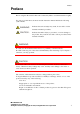
Preface Liquid crystal display (LCD) display characters The numeric LCD display is used to mimic alphabetic characters, as shown below: Alphabet Display Alphabet Display Numerals A N 0 B O 1 C P 2 D Q 3 E R 4 F S 5 G T 6 H U 7 I V 8 9 J W K X L Y M Z Display All display elements shown ON F00.EPS Note Regarding Panels Shown in this Manual: Panels shown in this manual should be regarded as examples.
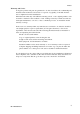
Preface Warranty and Service Yokogawa products and parts are guaranteed to be free from defects in workmanship and materials under normal use and service for a period of (typically) 12 months from the date of shipment from the manufacturer. Individual sales units may offer different warranty periods, so the original purchase order should be consulted for the conditions of sale.
Contents CONTENTS Preface ...................................................................................................................... 1-1 1. Outline ................................................................................................................. 1-1 1.1 1.2 1.3 1.4 1.5 1.6 1.7 1.8 Features ......................................................................................................................... Personal Conductivity Meter Specifications ..........................
1. Outline 1. Outline The Model SC72 Personal Conductivity Meter is an accurate, portable, easy-to-use conductivity meter. It includes not only self-diagnostic functions, to help ensure validity of readings, but also data storage functions to allow users to check past data. The meter is of waterproof construction so that it can safely be used outdoors on a rainy day, and can also withstand being accidentally dropped into water. 1.
1. Outline 1.2 Personal Conductivity Meter Specifications Applicable measurement range: • Sensors for high purity water measurement (cell constant: 0.
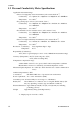
1. Outline EMC Compliance: EMI (Emission): EN 61326-1 Class B Test Item Frequency Range Basic Standard Electromagnetic radiation disturbance 30 to 1000 MHz CISPR 16-1 and 16-2 T0101.EPS EMS (Immunity): EN 61326-1 Table 2 (For industrial locations) No. 1 Test Item Electrostatic discharge Test Specification 4 kV (contact) 8 kV (air) Basic Standard Performance Criteria* IEC 61000-4-2 A 80 to 1000 MHz, 10 V/m (unmodulated) 80% AM (1 kHz) 2 RF amplitude modulated electromagnetic field 1.4 to 2.
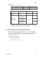
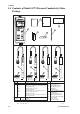
1. Outline 1.4 Contents of Model SC72 Personal Conductivity Meter Package Quick Manual 3 User's Manual Instrument Card 6 1 5 2 SC72 - - 4 - AA 7 9 8 10 11 11 SC72 - 11 - - AA *1 -23 -31 -41 Label language - -J -E - AA *1 - AA SC72 - 31 - Specification Personal conductivity meter Meter only, without sensor With sensor for high purity water measurement (cable length: 0.75m) With general-purpose sensor (cable length: 0.
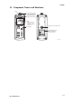
1. Outline 1.5 Component Names and Functions O-ring Sensor cable connector Used to connect a dedicated conductivity sensor to the personal conductivity meter. Can attach hand strap here Display Displays conductivity, temperature, and temperature coefficient simultaneously. Battery box cover fixing screw Key switches PERSONAL SC METER MODEL SC72 STYLE S1.0 No. Instrument name plate with model number and serial number E000001 2004. F010501.
1. Outline 1.6 Sensor Part Names and Functions Four types of sensors are available for use with the Model SC72 Personal Conductivity Meter: (1) sensor for high purity water measurement (cell constant 0.05 cm-1), (2) general-purpose sensor (cell constant 5 cm-1), (3) chemical-resistant sensor (cell constant 50 cm-1), and (4) sensor for high-conductivity measurement (cell constant 50 cm-1). Check the model number and cell constant on the name plate to confirm which type of sensor you have.
1. Outline Sensor for high purity water measurement SC72 - 11 - General-purpose sensor SC72 - 21 SC72 - 23 - - AA *1 Model number and cell constants display plate - AA - AA *1 Model number and cell constants display plate (SC72SN-11-AA) *1 (SC72SN-21-AA,*1 SC72SN-23-AA) Watertight cover Prevents moisture from entering connector and causing leakage between pins.
1. Outline 1.7 Options (Available Separately) The following options are available for the Personal Conductivity Meter for your convenience. When ordering, specify part number shown below. Standard solution (Part no.: K9221ZA) Soft case (Part no.: B9269KJ) Sensor stand (Part no.: K9220XN) Approx. 280 Unit: mm x. 140 0.1mol/l NaCl solution for calibration (250ml) . 30 rox Appro App This soft black carrying case holds conductivity meter and sensor.
2. Preparation 2. Preparation 2.1 Installing the Batteries Install the batteries first. CAUTION Select a relatively moisture-free location when installing batteries in the meter. When installing batteries, observe correct polarity (battery orientation). Failure to do so may damage to the meter. Remove batteries from the meter if it is to be stored for an extended period of time. Do not leave dead batteries in the meter. They may leak and cause meter failure or erratic operation of the meter.
2. Preparation 2.2 Connecting Sensor Cable Connect the sensor cable as shown below. CAUTION Select a relatively moisture-free location when connecting the sensor cable. When connecting the sensor cable, tighten by turning only the silver locknut, do not turn the cable or waterproof cover. Also take care not wet or contaminate the connector. Model SC82 sensors can be connected, but these are not guaranteed to be waterproof when used with this meter.
2. Preparation 2.3 Setting Date and Time After installing the batteries, set the date and time. Note that if the power is turned off before setting “minutes,” start with the date setting when you turn on the power next time. If you replace the batteries, the date is not affected, but the time is reset. Reenter the time. Caution:If the sensor is not connected then an error will be displayed on the meter. • Setting method After installing batteries, press and hold the POWER key for at least one second.
2. Preparation 2.4 Setting Temperature Unit Default temperature units are 8C. To change to 8F, refer to Sec. 4.3 (13) Set temperature units (tP.U) panel. 2.5 Setting Cell Constant Even for sensors of the same type, each sensor has its own distinct cell constant. So, set the proper cell constant as indicated on the sensor cable. Whenever sensors are replaced, be sure to change the cell constant setting in the meter accordingly.
2. Preparation F/ENT for Function mode select C.C F/ENT for C.C panel to enter C.C F/ENT MEAS F020501.EPS You can abort this procedure at any time by pressing MEAS to revert to measurement mode.
2. Preparation 2.6 Setting Temperature Compensation Coefficient As described in Section 7.3, liquid conductivity varies with liquid temperature. Therefore, if concentration is measured by conductivity, the conductivity must be converted to equivalent conductivity at a certain temperature. This instrument incorporates standard temperature conversion functions to convert liquid conductivity measurements to equivalent conductivity at 258C.
2. Preparation • Set the temperature compensation coefficient F/ENT for Function mode select t.Co F/ENT for t.Co panel For NaCl solutions Manual setting select NaCl or %/8C (%/8F) F/ENT Set the temperature compensation coefficient with the keys. F/ENT F/ENT MEAS MEAS The temperature coefficient you set is displayed here IM 12D03D02-01E F020601.
2.
3. Measurement 3. Measurement 3.1 Precautions (1) Be sure to check that the cell constant and the temperature coefficient are set correctly. (2) Check that the plastic cover (for general-purpose sensor) and outer electrode (for high purity water measurement) are secure. (3) Do not use the SC72 meter to measure liquids with temperatures over 808C. (If the sensor grip is immersed, liquid temperature shall be below 508C.
3. Measurement 3.2 Measurement Procedures Dipping sensor into liquid To help avoid errors due to air bubbles around the sensor element (inner electrode), immerse the sensor into the liquid to be measured so that its air vent is below liquid level. To dislodge any air bubbles from the inner electrode, dip the sensor into the liquid and move it up and down two or three times. Air vent Measuring liquid level Cover Electrode element If air bubbles are on this section, measurement error may occur. F0302.
3. Measurement 3.3 Measurement Panel Immerse the sensor into the liquid to be measured to display the liquid conductivity on the LCD display. There are three measurement panel display types: the standard display, calendar, and clock display. MEAS Use the key to toggle the display type.
3. Measurement (2) Data storage If the F/ENT DATA key is pressed during measurement, mark starts flashing. Press the key, then currently measured data can be stored in nonvolatile memory. Data stored are measured conductivity, measured temperature, date and time. Up to 300 data including individually deleted data can be stored. If you attempt to store more data, is displayed. If is displayed even though the number of data stored is less than 300, perform “defrag” [refer to Section 4.
4. Keyswitch Functions 4. Keyswitch Functions There are seven membrane keys on the keyboard of the Personal Conductivity meter. The following key functions are provided. * Display the conductivity, measured temperature and temperature coefficient. * Display the conductivity, date and time. * Hold conductivity and temperature measurements. * Store conductivity and temperature measured data. * Other functions such as parameter setting. When meter is OFF, press for at least 1 sec. to turn on power.
4. Keyswitch Functions 4.1 Names and Functions of Keys POWER : Power ON/OFF key If nothing is displayed on the LCD, hold down this key for about one second or more to turn the power on. If something is displayed on the LCD, pressing and holding this key for about two seconds turns power off. If no keys are pressed during a certain time interval, power turns off automatically (refer to “A.oFF,” Set Auto Power Off Interval of Section 4.3 (10)).
4. Keyswitch Functions F/ENT : Entry key In measurement mode, pressing this key switches the meter to function mode (see Section 4.3, “Function Modes”). This key is also used to confirm set values. Buzzer (Beep) sound When a key is pressed, the buzzer beeps. Where the buzzer beeps once, or when it beeps three times continuously, the meaning is as follows: (1) When the buzzer beeps once: This means that key operation was accepted.
4. Keyswitch Functions 4.2 Liquid Crystal Display and Display Items Displays and their explanations are shown below. Remaining battery life display Temp. compensation setting mode Manual range setting mode Data save mode HOLD mode Calibration with std. solution Cell constant set mode F040201.EPS (1) Remaining battery life display Remaining battery life is always displayed stepwise. When display is , battery is normal. When a flashing is displayed, battery power is low.
4. Keyswitch Functions 4.3 Function Modes Outline A variety of functions are supported by function mode. Press the F/ENT key to switch from measurement mode to function mode. This mode supports the functions listed in the table below. Note: The last selected and executed item is displayed when you switch to function mode. Pressing the keys displays the items listed in Table 4.1 in turn. Methods of setting items Use the keys to move to the desired item.
4. Keyswitch Functions Details about how to set each item are provided below. (1) Display stored measurement value (dAt) panel Used to display stored measurement values. mark appears in the top left corner of the display. The last-stored conductivity and temperature values are displayed first. The stored data item number flashes in the lower left corner.
4. Keyswitch Functions F/ENT to display other data Dsy, month data was stored Stored measurement data DATA Year that data was stored DATA Latest data DATA "Delete stored data" panel DATA Time stored F/ENT DATA F/ENT Delete stored data F/ENT When no stored data. F/ENT F040301.
4. Keyswitch Functions (2) Temperature compensation setting (t.Co) panel This panel is used to change the temperature compensation type and temperature coefficient setting. The TEMP mark appears on the panel. • Automatic temperature compensation for NaCl solution Press the keys to select NaCl . Then press the F/ENT key. • Manual temperature compensation coefficient setting Press the keys to select %/8C (or %/8F). Then press the keys to set the temperature coefficient. Then press the key.
4. Keyswitch Functions (3) Range selection (rnG) panel Change the current measuring range. Use the keys to change between autoranging and fixed range. For fixed range, mark appears. Relationships between automatic and fixed ranges for different sensors For general-purpose sensor (SC72-21, -23) *1 For chemical-resistant sensor (SC72-31) *1 Autorange Autorange Fixed range 5 (0-20.00mS/cm) Fixed range 5 (0-20.00mS/cm) Fixed range 4 (0-200.0mS/cm) Fixed range 4 (0-200.0mS/cm) Fixed range 3 (0-2.
4. Keyswitch Functions (4) Cell constant setting (C.C) panel This panel with the Use the mark is used to set the cell constant manually. keys to set the cell constant. Then press the F/ENT key. Typical cell constants are as follows: For pure water sensor (SC72-11): 0.
4. Keyswitch Functions (5) Calibration with standard solution (CAL) panel This panel is used for calibration with standard solution. Refer to Sec. 5.4 for a description of the calibration procedure. In CAL mode, the mark appears at the top of the panel and all digits of the present measurement value flash. After the measurement stabilizes, press the F/ENT key to display the measured value at that time. Only the least significant digit flashes.
4. Keyswitch Functions (6) Delete all stored measuring data (dEL.A) panel This panel is used for deleting all stored data. When you switch to this panel, Press the F/ENT is flashing. Use the keys to select . key to delete all the data completely. F/ENT to set F/ENT to abort F/ENT to execute delete all F040306.EPS (7) Date setting (dAtE) panel Set the date for the meter; year (four digits), month, day in order. Use the keys to set year, month, and day.
4. Keyswitch Functions (8) Time setting (tIME) panel For the converter, set the time (24-hour display), minutes in order. Use the keys to set hours and minutes. Then press the F/ENT key to complete setting. Hour setting (24-hr clock) Minute setting F/ENT F/ENT F/ENT F040308.
4. Keyswitch Functions (9) Alarm time setting (ALM) panel Alarm Enable (ON) / Disable (OFF) and alarm occurrence time (hours and minutes) can be set. Use the keys to set alarm time. Alarm time setting methods are the same as for (8) Time setting (tIME). Alarms sounds for about 15 seconds continuously. Acknowledge alarm by pressing any key to stop alarm sound. If no key is pressed to acknowledge the alarm occurrence, alarms sound for 15 seconds again three and six minutes after the preset alarm time.
4. Keyswitch Functions (10) Set Auto Power Off interval (A.oFF) panel Set the time interval for the power to turn off automatically if no key is pressed during a preset time interval. The Interval can be set to between 1 and 120 minutes. If “0 minutes” is set, automatic power OFF functions are disabled, so — without some care — batteries won’t last very long. Use key to set F/ENT to confirm F/ENT F040310.EPS (11) Set buzzer ON/OFF (bZ.
4. Keyswitch Functions (12) Set measurement unit (SC.U) panel Toggle the measurement value units between [S/cm] and [S/m]. Use the keys to toggle the measurement value units. Then press the key F/ENT to complete setting. F/ENT to toggle F/ENT to set F040312.EPS (13) Set temperature unit (tP.U) panel Toggle the temperature units between [8C] and [8F]. Use the keys to toggle the temperature units. Then press the F/ENT key to complete setting. F/ENT to toggle F/ENT to set F040313.
4. Keyswitch Functions (14) Version number dispaly (VEr) panel Displays program firmware version number. Can’t be set by the user. F/ENT F040314.
4. Keyswitch Functions (15) Defragment storaged data (dFLG) panel Up to 300 data can be stored. Unnecessary data can be individually deleted as in (1) Stored measurement data panel (dAt). At the same time, individual deletion does not free up memory occupied by deleted data, so may be displayed even though less than 300 data are stored. In such a case, use defrag functions to compact storage and free up the space occupied by deleted data, thereby allowing up to 300 data to be stored.
5. Handling of the SC72 Personal Conductivity Meter 5. Handling of the SC72 Personal Conductivity Meter 5.1 Tips to Maintain Meter Performance The SC72 meter appears to be very simple, but is a precision instrument. To ensure that measurement accuracy is maintained, observe the following precautions regarding preliminary setting, measurement, maintenance and storage. Preliminary setting, measurement, maintenance and storage: Measurement Preliminary setting Maintenance Storage F050101.EPS Table 5.
5. Handling of the SC72 Personal Conductivity Meter 5.2 Washing the Electrode Dirt or stains on the electrode may have an adverse effect on the cell constant, thereby making accurate conductivity measurement impossible. Therefore, after measurement, rinse the electrode in clean water (for example, tap water) to remove stains. Even if staining is not apparent, the sensor performance may have changed. If so, wash the electrode by moving the sensor up and down in hydrochloric acid (about 0.
5. Handling of the SC72 Personal Conductivity Meter 5.3 Cleaning and Drying Connector If there is an electrical path between the connector pins, solution conductivity cannot be measured correctly. Clean the connector (shown in the figure) with a dry cloth, or a cloth moistened with pure undiluted alcohol, to remove moisture and/or stains. If necessary, use a hair dryer to dry any section that is likely to be difficult to wipe. O-ring Wipe off stains and/or moisture on meter connector with a dry cloth.
5. Handling of the SC72 Personal Conductivity Meter 5.4 Calibration with Standard Solution Note: Calibration with standard solution means to measure a standard solution of accurately-known conductivity and to adjust SC72 meter so that the displayed measured value is the same as the known conductivity value of the standard solution. If the sensor has been used for a long time, and does not look clean despite washing, recalibrate the SC72 meter with standard solution to check if cell constant is normal.
5. Handling of the SC72 Personal Conductivity Meter * Before calibrating the meter with standard solution, check that the electrode is clean. If stains are found, clean the electrode first. Also check that the cover (of general-purpose sensor) and outer electrode (of sensor for high purity water measurement) are secure. Cell constant is affected by stains or loose cover. When calibrating, ensure that measuring range is set so that you can enter conductivity to as many digits as possible.
5. Handling of the SC72 Personal Conductivity Meter Procedures for calibration with standard solution POWER Water F/ENT Std. sol. Wash sensor with water completely. Select Thoroughly wipe off the CAL mode washing water from the electrodes before immersing the sensor in standard solution. F/ENT Least significant figit of the measuremet value is flashing Whole measurement value is flashing F/ENT Wait until the measured value is stable. Set the conductivity of the standard solution.
5. Handling of the SC72 Personal Conductivity Meter 5.5 Storage and Maintenance • Method of storage Care is required when storing the SC72 meter. To maintain the SC72 meter in good condition, observe the following: (1) After measurement, thoroughly wash the sensor in water. (2) Leave the sensor connected to the meter body, to protect the connector from staining.
5. Handling of the SC72 Personal Conductivity Meter (1) Replacing O-rings Install the O-ring on the cylindrical flat part as shown in the figure. O-ring F050501.EPS (2) Replacing gaskets Install the gasket with its raised part facing downwards on the groove of th meter case. Gaskets are symmetrical (on the right and left, and on the front and rear). Gasket SC72 meter top Raised part F050502.
6. Troubleshooting 6. Troubleshooting 6.1 Causes of Abnormal Conductivity Display The measured temperature is stable, but the conductivity reading is unstable, or an unrealistic value is displayed, check the following: (1) Is maintenance required, and has handling of the meter been adequate? (2) Does the battery need replacement? (3) Is SC72 meter unserviceable? If any problem is evident, follow the procedure shown in Section 6.2 to determine the cause and fix the problem.
6. Troubleshooting 6.2 Error Messages and Corrective Action Table 6.1 Error message Error Message *1 Name Err1 Temperature compensation computation value out of range Err2 Out of temperature measurement range Err3 Calibration error Err6 Meter electronics failure or Out of measuring range *1 Alphabet values simulated on a numeric display (1) Err1 T0601.
6. Troubleshooting (3) Err3 Calibration error Cause: When the calibration with standard solution is made, each time cell constants are changed. Err3 occurs if the conductivity of the standard solution is wrong, or changed cell constants are beyond 6 20% of the standard cell constant, due to a damaged sensor. Corrective action: * Use correct standard solution conductivity. (Refer to Sec. 5.4) * Replace the sensor. (Refer to Sec. 1.
6. Troubleshooting 6.3 Causes of Abnormal Measured Value If error messages do not occur, but measured values seem incorrect, check the following: * Are cell constants and temperature coefficients correctly set? * Is the sensor properly connected to the meter? * Are bubbles attached to the electrode portion? * Is the sensor damaged or dirty? 6.4 Other conditions • An alarm sounds The alarm clock is set (see Sec. 4.3 (9) and change setting as required).
7. Measuring Principles of this Instrument 7. Measuring Principles of this Instrument 7.1 What Is Conductivity? Conductivity of a solution is defined as the ability of the solution to conduct electric current. It is the reciprocal of the resistance between two sensors (both of areas 1 m2) at a distance of 1 m apart in the solution. 1 S/cm = 100 S/m Figure 7.1 shows the conductivities of typical solutions. 0.01 0.1 0.
7. Measuring Principles of this Instrument 7.2 Principles of Operation AC power supply Ammeter F0702.EPS Figure 7.
7. Measuring Principles of this Instrument 7.3 Temperature Compensation and Finding Temperature Compensation Coefficient • Temperature Compensation Table 7.1 shows the conductivity ratio at each liquid temperature when the conductivity of a NaCl solution at 258C is 1. Table 7.1 Conductivity Ratios at Different Temperatures in NaCl solutions 08C 258C 508C 758C 1008C 0.542 1 1.531 2.103 2.677 T0701.EPS As shown in the above table, liquid conductivity changes with liquid temperature.
7. Measuring Principles of this Instrument K2 2 K 1 Temp. coef. a = K 1 ( t 2 2 25 ) 2 K 2( t 1 2 25 ) where 3 100 (%/8C) t 1, t 2: liquid temperature (8C) K1 : conductivity at t 1 K2 : conductivity at t 2 (Calculation example) To find the temperature coefficient of liquid with conductivity - 124.5 (S/cm at liquid temperature 18.08C and 147.6 (S/cm at liquid temperature 31.08C, substitute t1 = 18.0, t2 = 31.0, K1 = 124.5, K2 = 147.6 in the equation above, thus we can obtain: a= = 147.6 2 124.5 124.
Appendix Appendix Key-Operation Flow Chart (for reference) Typical screens are shown. Refer to the corresponding section in the body of the manual for details. d When turn on power Toggle display type POWER or First time used, or after replace batteries MEAS F/ENT MEAS F/ENT MEAS F/ENT d Temporary hold HOLD HOLD MEAS F/ENT F/ENT d Storing data DATA F/ENT DATA MEAS T01.
Appendix d Function Mode Temperature compensation setting Range selection Display stored measurement value F/ENT F/ENT F/ENT F/ENT or DATA F/ENT DATA F/ENT F/ENT F/ENT DATA DATA F/ENT F/ENT T02.
Appendix d Function Mode Cell constant setting Calibration with standard solution F/ENT F/ENT F/ENT Delete all stored measurement data Date setting F/ENT F/ENT F/ENT F/ENT Time setting F/ENT F/ENT F/ENT F/ENT F/ENT F/ENT F/ENT d Switching to Function Mode d Reverting to Measurement Mode Measurement status Measurement status MEAS F/ENT T03.
Appendix d Function Mode Alarm time setting Set Auto Power OFF Set buzzer ON/OFF interval F/ENT F/ENT Set measurement unit Set temperature unit F/ENT F/ENT F/ENT F/ENT F/ENT F/ENT F/ENT F/ENT F/ENT d Function Mode Version number display F/ENT Deflagment storaged data F/ENT F/ENT T04.
Revision Record Manual Title : Model SC72 Personal Conductivity Meter Manual Number : IM 12D03D02-01E Edition 1st 2nd Date Aug. 2004 Apr. 2008 3rd Aug. 2009 Remark (s) Newly published Addition of information on EMC compliance: P.1-3 Addition of CAUTION: P2-2 Correction: P.1, 1-2, 1-6, 2-1, 2-3, 3-1, 3-3, 4-1. 4-5, App-1, App-4 Change of information on EMC compliance: P.