
Instruction Manual


4-22
IM 01R04B04-00E-E 8th edition March 01, 2011 -00
All Rights Reserved. Copyright © 2003, Rota Yokogawa
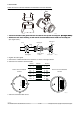
Example of installation :
F418.EPS
Hazardous area
Iout +
Iout -
R barrier
4-20mA
Vin
V out
Ground
Safe area
ROTAMASS
/KF2
R load
HART communication is available on analog output 1 and the HART-communicator is connected via load
resistance (230 ... 600 Ω) as shown on the gure below.
HART
Communicator
HART
Communicator
HART
Communicator
Intermediate
terminals
4 to 20mA DC
signal trans-
mission line
Receiving
instrument
Terminal board
Control room
F417.EPS
ROTAMASS
ROTAMASS with option /KF2 has one intrinsic safe current output and one intrinsic safe pulse / status
output. The Ex-data of this output can be found in chapter 9.1.
The second current output, the second pulse / status output and the status input are not available.
The concerning parameters in the menu are not visible.
The intrinsic safe current output is passive and an external power supply
with shunt-diode
type barrier or isolation type barrier should be connected.