
Instruction Manual


4-18
IM 01R04B04-00E-E 8th edition March 01, 2011 -00
All Rights Reserved. Copyright © 2003, Rota Yokogawa
• Use cables with cross section 0.08 to 0.5 mm²
• Connect the cables from the external instruments to the terminals inside of the converter terminal box
(RCCT3 / RCCF31 or on terminal board (RCCR31).
• Conrm two ferrite core sets are attached to the owmeter.
• Insert the cable into ferrite core before connecting to the terminals. Fix the ferrite core (see gure on
page 4-16)
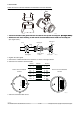
• Connect the cables to the terminals according to the gure below.
I/O-Terminal Overview :
Receiving instrument
ROTAMASS
Iout -
Iout +
+
-
-
Load resistance max. 600 Ω
F411.EPS
1. Analog signal output (Iout 1 and Iout 2)
ROTAMASS has 2 analog outputs, 4 to 20 mA DC.
Load resistance 20- 600 Ω (/KF2 has only one analog output, which is intrinsic safe. See chapter 4.8.8).