
Instruction Manual


4-17
IM 01R04B04-00E-E 8th edition March 01, 2011 -00
All Rights Reserved. Copyright © 2003, Rota Yokogawa
CAUTION
Special connections for Ex version :
The converter case must be connected to the potential equalisation facility of the
hazardous area , e.g. to the U-clamp PA terminal on the outside at the converter. Please refer to chapter 9
“EXPLOSION PROTECTED TYPE INSTRUMENTS”.
Cable : Use cables acc. to VDE 0250, VDE 0281 or equivalents.
Outer diameter : DIN and NPT cable gland: 6.5 to 10.5 mm in diameter
Nominal cross section of conductive wire : 0.5 to 2.5 mm²
Outer diameter of cores insulation part : < 3.6 mm
Connecting length of conductive wire part : < 9 mm
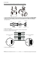
For the DC power supply type, connect a 24 V DC power supply, following the precautions below.
1. Connecting Power Supply
Please refer to the Figure in right. AC power supplies
can not be connected. Conrm the polarity of DC power
supply.
2. Supply voltage rating
The specication for the supply voltage is 20.5 – 28.8 V DC. But because the input voltage
of the converter
drops due to cable resistance, it should be used within the following range.
3. Ground connection
Connect ground as shown on page 4-8 due to EMC protection.
L/+ N/- G
+ -
20.5 to 28.8 V DC
F49.EPS
1000
(3300)
900
(2970)
800
(2640)
700
(2310)
600
(1980)
500
(1650)
400
(1320)
300
(990)
200
(660)
100
(330)
0
20 22 24 26 28 30
F410.EPS
Allowed
cable length
m (ft)
Cable crosssection area 1.25mm
Cable crosssection area 2mm
voltage V