
Instruction Manual


4-16
IM 01R04B04-00E-E 8th edition March 01, 2011 -00
All Rights Reserved. Copyright © 2003, Rota Yokogawa
• Connect the power supply cable to the terminals inside of the converter terminal box (RCCT3 /RCCF31)
or on terminal board (RCCR31).
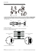
• Conrm two ferrite core sets are attached to the owmeter.
• Insert the cables into ferrite core before connecting to the terminals. Fix the ferrite core to the cable with
clamping wire.
• Connect the power cables to the terminals according to the gure below.
• For the connection of protective ground conductor to PE terminal of RCCF31 / RCCT3 use a crimp-on
ring type terminal. For RCCR31 connect the protective ground conductor to PE terminal of terminal
board.
RCCT3 / RCCF31 RCCR31
CAUTION
1. Before starting the wiring, turn off the source of the supply power and check with the tester that there is
no voltage at the cable.
2. For RCCT3 / RCCF31 the protective ground conductor must be connected to the separate PE terminal
in the terminal box with Crimp-on ring-type terminal in order to avoid personal shock hazard.
2. For RCCR31 the protective ground conductor must be connected to the separate PE terminal on the
terminal board in order to avoid personal shock hazard.
3. An exclusive external circuit breaker must be placed near each owmeter.
4. Check the external circuit breaker’s rating conforms to the requirements specied in the specication of
this instrument.
5. Wire the power supply cable keeping the distance of 1 cm or more from other signal wires.
6. Conrm the operating voltage of the converter before operation.
7.
Please lock the cover of the converter with hexagon lock screw before operation (only RCCT3 /RCCF31)