
Instruction Manual


4-7
IM 01R04B04-00E-E 8th edition March 01, 2011 -00
All Rights Reserved. Copyright © 2003, Rota Yokogawa
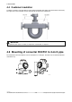
If the remote rack mount converter RCCR31 was not ordered with option /SR1 or /SR2, the customer has
to mount it to an own 19´´ subrack. The terminal board must be xed by 6 screws (M2.5x10) to the rear
side of the subrack.
The RCCR31 rack cassette must be inserted into the subrack.
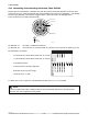
LCD display can be turned its direction with respect to piping congurations.
Removing four screws, adjusting display’s orientation and xing the screws tightly again as shown in gure
below.
Fix the lock screw for use in hazardous area. After modication the user must ensure that the cover is
screwed down tightly to maintain the IP rating of the housing, failure to do so may allow moisture
ingress and failure of electronic components.
F43.EPS
Lock screw for cover (Ex d)
IMPORTANT